Within 1 second, press Include button of
PAN28 again for 5 seconds.
IDs are excluded. 2s On, 2s Off (No node ID)
※Adding a node ID allocated by Z-Wave Controller means inclusion. Removing a node
ID allocated by Z-Wave Controller means exclusion.
※Failed or success in including/excluding the node ID can be viewed from the Z-Wave
Controller.
※ Sometimes people are not easy to execute exclusion or inclusion especially when PAN28
already installed in a wall box. To solve this issue, PAN28 support a special feature that can
use S1 or S2 to execute “exclusion, inclusion, Reset or Association” at the first 3 minutes when
first time connect to main power.
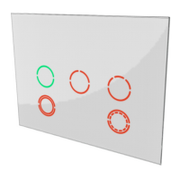
LED Indication
There is a LED for identify function in the front case. PAN28 support the indicator ID
0x50 (Identify) and Properties ID 0x03, 0x04 and 0x05.
To distinguish what mode the switch is in, view from the LED for identification.
State Type LED Indication
Normal When PAN28 switch On the LED will lights up, when PAN28 switch Off
the LED will lights off.
No node ID Under normal operation, when the Switch has not been allocated a
node ID, the LED flashes on and off alternately at 2-second intervals.
Overload When overload state occurs, the Switch is disabled of which LED
flashes on and off alternately at 0.2 second intervals. Overload
state can be cleared by disconnect and reconnect the Switch to
the main power.
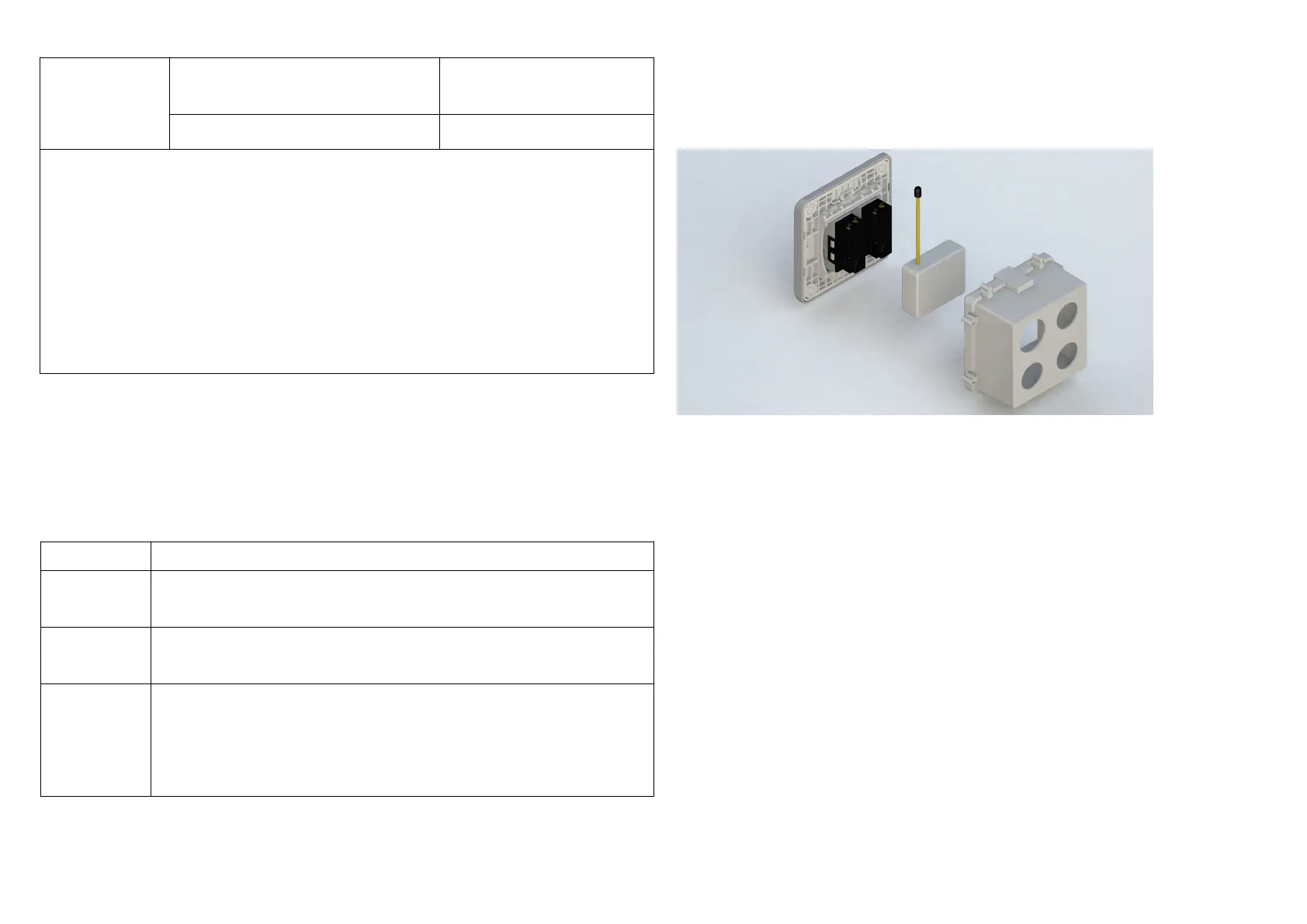
Installation
1. Put the in wall switch into a wall box and connect the AC power wire L, N to
PAN28 connector L, N.
2. Connect the wall switch to the PAN28 as Fig1.
3. There are 3 mode PAN28 can be configured to match different kind of wall
switch, please refer to 3-1 External switch mode which described in next
section of this user manual
4. If Edge-Toggle mode has been set, and the S1/S2 is connect to normal bi-
stable switch, every time when change the state of the wall switch will also
swap the state of Relay1.
Programming
1. Basic Command Class / Binary Switch Command Class
5
 Loading...