4. OPERATION
The display shows the tank levels automatically after switching on.
In the SETUP-menu you can adjust each tank-display individually to the medium (fuel, water...), to the type of
sensor used, to the compensation value for the tank-geometry and the alarm-threshold. In case of a power sup-
ply breakdown all of these adjustments are saved and immediately available after switching on.
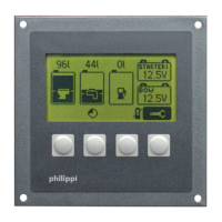
The tank levels are measured each 5 s. The measured levels are shown in a bar diagram and additonally
either in litres, in percent or without further indication. This can be adjusted in the SETUP-menu.
If the indication over a tank is “----”, the measured value of the related tank is out of an expected value or there
is no sensor connected.
If an alarm threshold for a tank is set up , this threshold is shown by a little triangle on the side of the bar.
So you have a quick overview if the tank level is inside of the correct range.
If the threshold is over 50%, the full -alarm is on, i.e. a filling level over the threshold set off the alarm.
If the threshold is below 50% the empty - alarm is on, i.e. a filling level below the threshold sets off the alarm.
In case of an alarm the related tank symbol is blinking and a buzzing signal is sounding for the preset time.
The alarm can be acknowledged by you when pressing a button
To reduce the current consumption when using ultrasonic sensors (ca. 50mA / sensor), you can choose the
Powersave Mode. Please note: when using the Powersave mode, the alarm is deactivated too!
In the Powersave mode the measurement is carried out every 30 min. (11 ,5-13 V) and every 2 hours
(below 11,5 V). The Powersave mode is activated automatically if the supply voltage goes below 11,5 V to save
the batteries life. Under 10V no measurement takes place.
In 24V- operation double values are applying.
k
TANKMONITOR TCM4
V2.3 - August 2011 Page 5
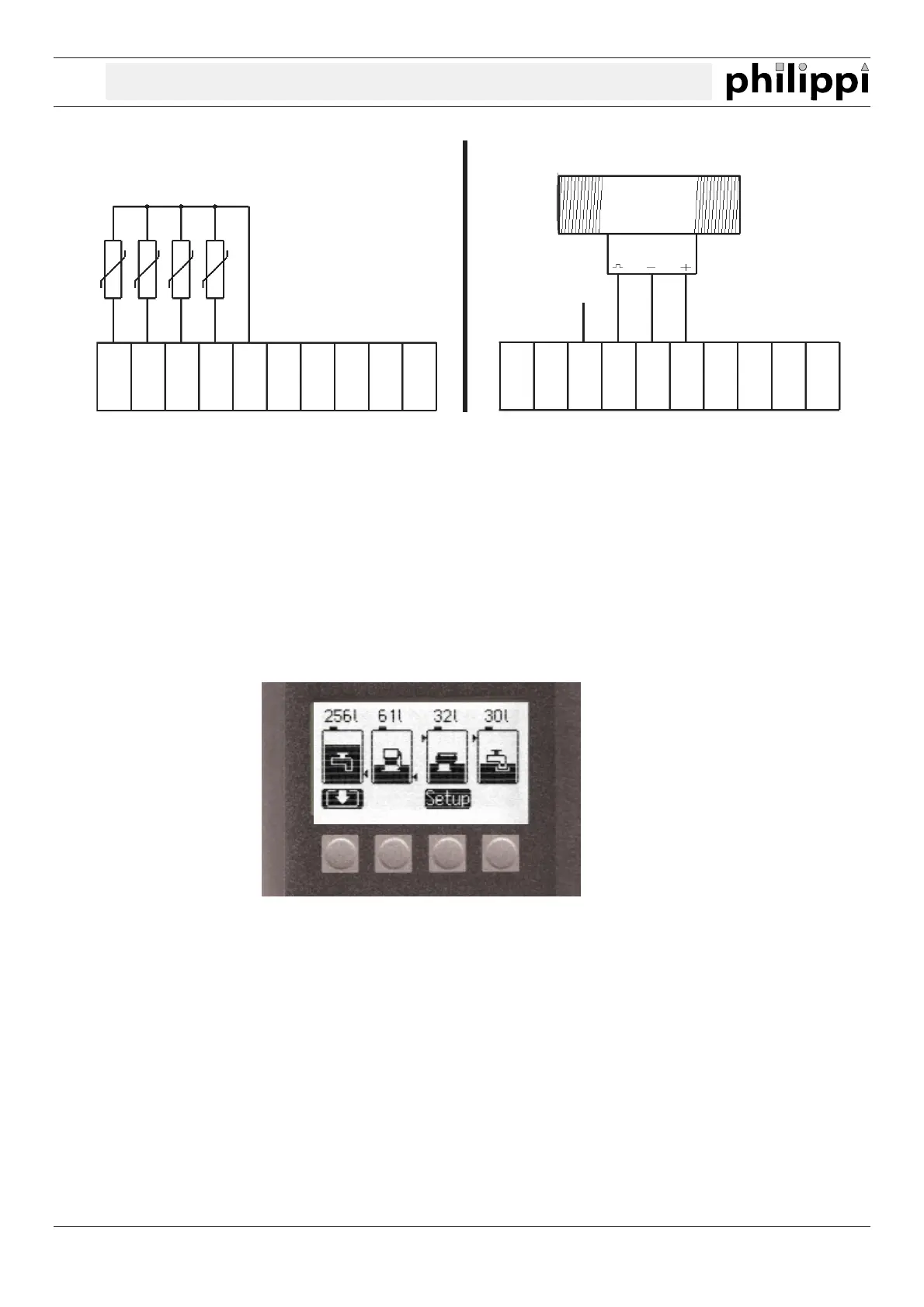
Connection of passive (resistance) sensors like TGT /
TGW and other:
Connection of flow sensors DFS:
Light
GND -
12/24V
UTV +
DFS +
GND -
TG 1
TG 2
TG 3
TG 4
Light
GND -
12/24V
UTV +
DFS +
GND -
TG 1
TG 2
TG 3
TG 4
(2.DFS)