Service Modes and Fault Finding
EN 17TPS14.1A LA 5.
2014-Oct-24
back to
div.table
5. Service Modes and Fault Finding
Index of this chapter:
5.1 Test Points
5.2 Service Modes
5.3 Stepwise Start-up
5.4 Software Upgrading
5.5 Fault Finding and Repair Tips
5.1 Test Points
As most signals are digital, it will be difficult to measure
waveforms with a standard oscilloscope.
Perform measurements under the following conditions:
• Service Default Mode.
• Video: Colour bar signal.
• Audio: 3 kHz left, 1 kHz right.
5.2 Service Modes
The Service Mode feature is split into five parts:
• Factory Mode.
• Customer Service Mode (CSM).
The Factory mode offer features, which can be used by the
Service engineer to repair/align a TV set. Some features are:
• Make alignments (e.g. White Tone), reset the error buffer
(Factory Mode).
The CSM is a Service Mode that can be enabled by the
consumer. The CSM displays diagnosis information, which the
customer can forward to the dealer or call centre. In CSM
mode, “CSM”, is displayed in the top right corner of the screen.
The information provided in CSM and the purpose of CSM is to:
• Increase the home repair hit rate.
• Decrease the number of nuisance calls.
• Solved customers’ problem without home visit.
Note: For the new model range, a new remote control (RC) is
used with some renamed buttons. This has an impact on the
activation of the Service modes. For instance the old “MENU”
button is now called “HOME” (or is indicated by a “house” icon).
5.2.1 General
Next items are applicable to all Service Modes or are general.
Software Identification, Version, and Cluster
The software ID and version will be shown in the main menu
display of CSM.
The screen will show: “AAAAB-X.YYY”, where:
• AAAA is the chassis name: TPS141A x.yyy.
• B is the region indication: E = Europe, A = AP/China, U =
NAFTA, L = LATAM.
• X is the main version number: this is updated with a major
change of specification (incompatible with the previous
software version). Numbering will go from 1 - 99 and
AA - ZZ.
- If the main version number changes, the new version
number is written in the NVM.
- If the main version number changes, the default settings
are loaded.
• YYY is the sub version number: this is updated with a minor
change (backwards compatible with the previous
versions). Numbering will go from 000 - 999.
- If the sub version number changes, the new version
number is written in the NVM.
- If the NVM is refreshed, the software identification,
version, and cluster will also be written to NVM.
5.2.2 Contents of the Factory mode:
Purpose
• To perform extended alignments.
Specifications
• Displaying and or changing Panel ID information.
• Various software alignment settings.
• Testpattern displaying.
• Public Broadcasting Service password Reset.
•etc.
How to Activate the Factory mode
To activate the Factory mode, use the following method:
• Press the following key sequence on the remote control
transmitter: from the “Home screen” press “1999”, directly
followed by the “Back” button. Do not allow the display to
time out between entries while keying the sequence.
After entering the Factory mode, the following items are
displayed,
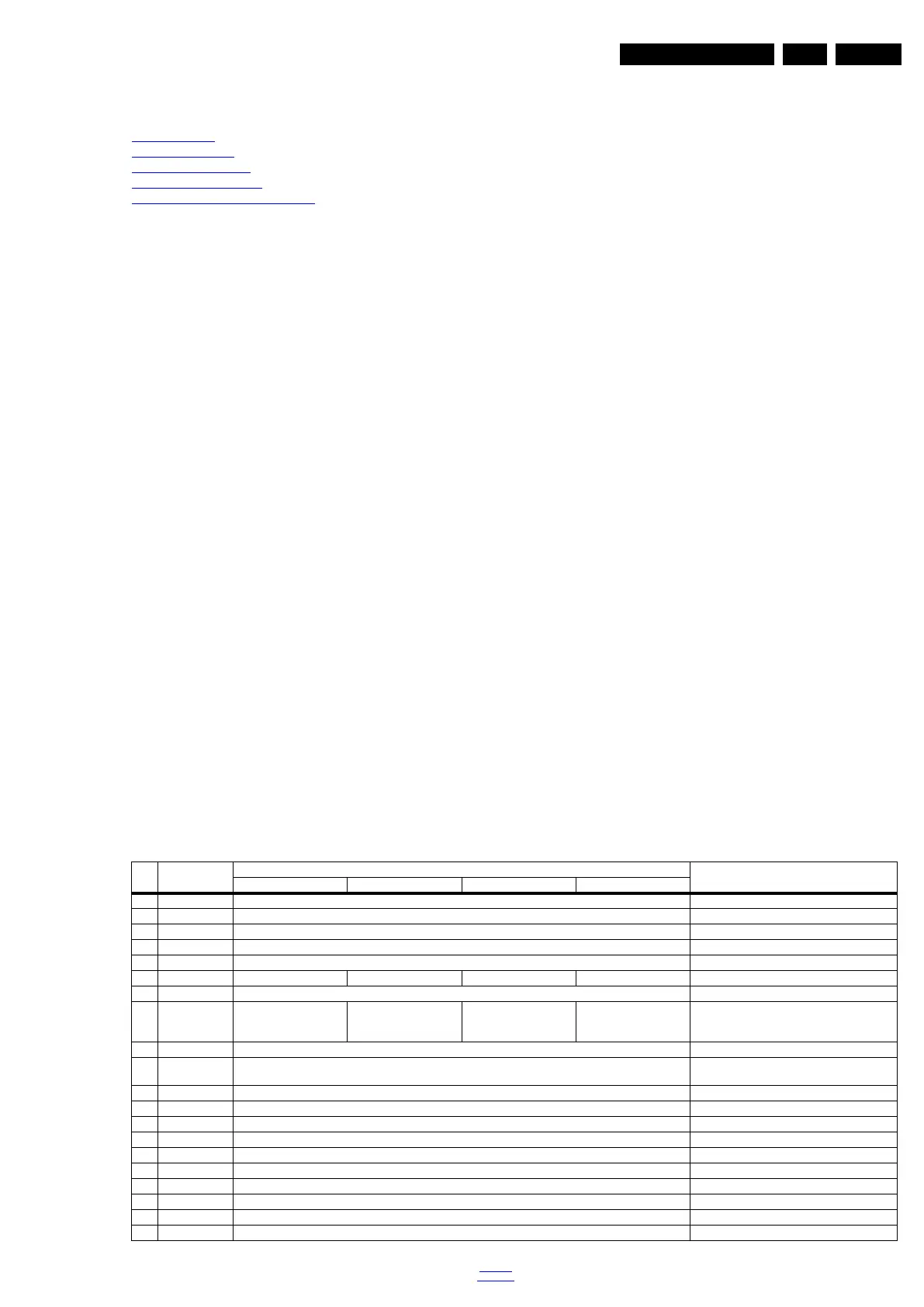
Table 5-1 Factory mode overview
Item Item value
Default value
Description24" 32" 40" 50"
0 Main-MCU Ver TPS1011A_V2.00 Main-MCU Version
1 Bootloader Ver V0.01 Bootloader Version
2 Sub-MCU Ver V0.01 SUB-MCU Version
3 EEPROM Ver V0.01 EEPROM Version
4 Date Feb 18 2014 Software release date
5 ModelName 24PHA4509 32PHA4509 40PFA4509 50PFA4509 Model name
6 Scaler MST6931XP Scaler model
7 Panel Type LCM236BJ103A01AX0F
&
LVM236BJ101A12CP0F
LVA315XVN02AE2210X
&
LVO315A0550AD62T0X
LCM400J6LE1AD1A10X
&
LVM400J6PE1AD92P0X
LCM500J1PE8ADQA50X Display model
8 Source TV Input source
9 Auto Color GO Only need to do automatic correction input
source of effective,otherwise it is not action
10 W/B Pattern OFF W/B Pattern
11 SSC SSC
12 Enable OFF Enable on/off
13 LVDS Span 35.0KHz LVD Span
14 LVDS Step 2.00% LVD Step
15 ADC YPbPr(SD) ADC
16 Gain RGB ADC Gain
17 Offset RGB Offset RGB
18 ColorTemp Normal The current set of color temperature
18 Scaler MST6931XP Scaler model