Technical Specs, Diversity, and Connections
EN 5TPS14.1A LA 2.
2014-Oct-24
back to
div.table
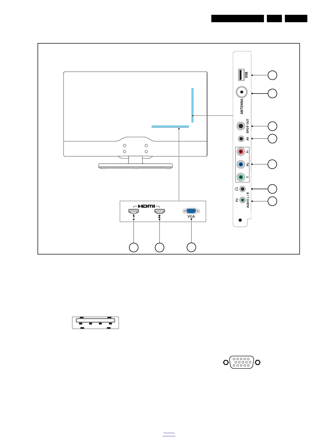
2.4 Connections (for 32"/40"/50"PxA4509 series)
Figure 2-6 Connection overview
Note: The following connector colour abbreviations are used
(acc. to DIN/IEC 757): Bk= Black, Bu= Blue, Gn= Green,
Gy= Grey, Rd= Red, Wh= White, Ye= Yellow.
2.4.1 Side Connections
1 - USB2 2.0
Figure 2-7 USB (type A)
1-+5V k
2 - Data (-) jk
3 - Data (+) jk
4 - Ground Gnd H
2 - TV ANTENNA - In
Signal input from an antenna, cable or satellite.
3 - Cinch: Digital Audio - Out
BK - Coaxial 0.4 - 0.6V
PP
/ 75 kq
4 - AV - In
Video and Audio L/R input.
5 - Cinch: Video YPbPr - In
Gn - Video - Y 1 V
PP
/ 75 W jq
Bu - Video - Pb 0.7 V
PP
/ 75 W jq
Rd - Video - Pr 0.7 V
PP
/ 75 W jq
6- Head phone (Output)
Bk - Head phone 80 - 600 W / 10 mW ot
7 - Audio - In: Left / Right, VGA
Bu - Audio L/R in 0.5 V
RMS
/ 10 kW jq
2.4.2 Rear Connections
8 - PC IN:VGA
Figure 2-8 VGA connector
1 - Video Red 0.7 V
PP
/ 75 W j
2 - Video Green 0.7 V
PP
/ 75 W j
3 - Video Blue 0.7 V
PP
/ 75 W j
4-n.c.
5 - Ground Gnd H
6 - Ground Red Gnd H
1 2 3 4
10000_022_090121.eps
090121
1
6
10
11
5
15
10000_002_090121.eps
090127