div. table
10000_050_100409.eps
100409
2010-04-09
1
3122 785 1000
SRP LIST EXPLANATION
1.1. Introduction
Example
SRP (Service Reference Protocol) is a software tool that creates a list with all references to signal lines. The list contains
references to the signals within all schematics of a PWB. It replaces the text references in the past printed next to the signal
names in the schematics. These printed references were created manually and are therefore not guaranteed to be 100%
correct. In addition, in the current crowded schematics there is often none or very little place for these references.
1.2. Non-SRP Schematics
There are several different signals available in a schematic:
1.2.1. Power Supply Lines
All power supply lines are available in the supply line overview (see chapter 9). In the schematics (see chapter 10) is not
indicated where supplies are coming from or going to.
It is however indicated if a supply is incoming (created elsewhere), or outgoing (created or adapted in the current schematic).
+5V +5V
Outgoing Incoming
1.2.2. Normal Signals
For normal signals, a schematic reference (e.g. B14b) is placed next to the signals.
signal_name
B14b
1.2.3. Grounds
For normal and special grounds (e.g. GNDHOT or GND3V3 etc.), nothing is indicated.
1.3. SRP Schematics
SRP is a tool, which automatically creates a list with signal references, indicating on which schematic the signals are used.
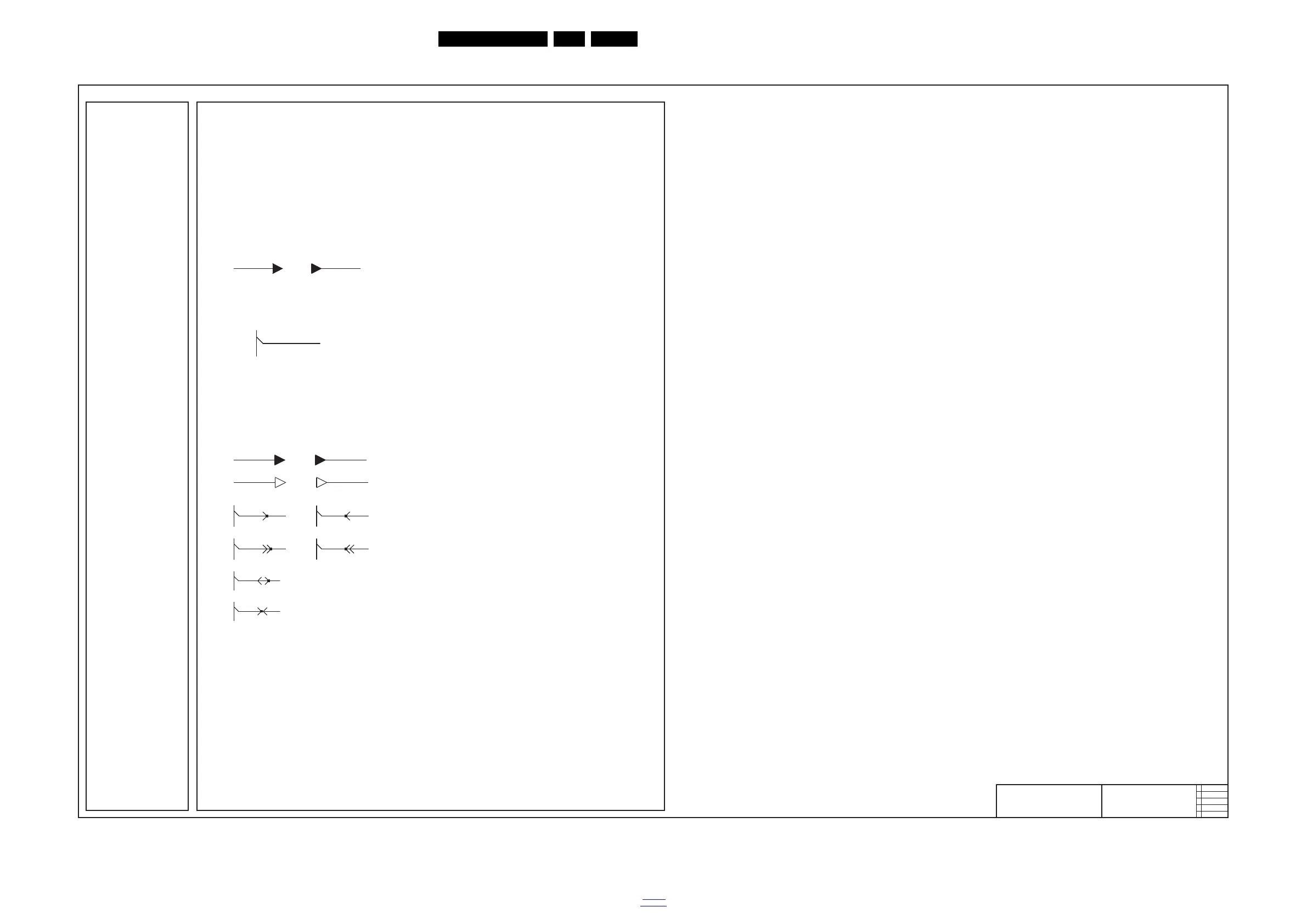
A reference is created for all signals indicated with an SRP symbol, these symbols are:
+5V +5V
Power supply line.
name name
Stand alone signal or switching line (used as less as possible).
name name
Signal line into a wire tree.
name name
Switching line into a wire tree.
name
Bi-directional line (e.g. SDA) into a wire tree.
name
Signal line into a wire tree, its direction depends on the circuit (e.g. ingoing for PDP, outgoing for LCD sets).
Remarks:
• When there is a black dot on the “signal direction arrow” it is an SRP symbol, so there will be a reference to the signal
name in the SRP list.
• All references to normal grounds (Ground symbols without additional text) are not listed in the reference list, this to keep
it concise.
•
Signals that are not used in multiple schematics, but only once or several times in the same schematic, are included
in the SRP reference list, but only with one reference.
Additional Tip:
When using the PDF service manual file, you can very easily search for signal names and follow the signal over all the
schematics. In Adobe PDF reader:
• Select the signal name you
want to search for, with the “Select text” tool.
• Copy and paste the signal name in the “Search PDF” tool.
• Search for all occurrences of the signal name.
• Now you can quickly jump between the different occurrences and follow the signal over all schema tics . It is advised to
“zoom in” to e.g. 150% to see clearly, which text is selected. Then you can zoom out, to get a
n overview of the complete
schematic.
PS. It is recommended to use at least Adobe PDF (reader) version 6.x, due to better search possibilities in this version.
Net Name Diagram
+12V B03B (1 ×)
+12V B03C (1 ×)
+12VD B03C (1 ×)
+12VD B03H (1 ×)
+1V1 B03E (2 ×)
+1V2 B02H (1 ×)
+1V2 B03D (1 ×)
+1V2-BRA-DR1 B01G (1 ×)
+1V2-BRA-VDDC B01G (1 ×)
+1V8 B02B (1 ×)
+1V8 B05A (5 ×)
+24V B13 (2 ×)
+24V-AUDIO-POWER B02D (1 ×)
+24V-AUDIO-POWER B03A (2 ×)
+24V-AUDIO-POWER B03C (1 ×)
+24V-AUDIO-VDD B02D (4 ×)
+2V5 B02D (1 ×)
+2V5 B03E (1 ×)
+2V5-AUDIO B02D (1 ×)
+2V5-AUDIO B02H (2 ×)
+2V5-BRA B01K (3 ×)
+2V5-LVDS B02H (2 ×)
+2V5-LVDS B03D (1 ×)
+2V5-REF B03D (3 ×)
+3V3 B04A (3 ×)
+3V3 B04C (8 ×)
+3V3 B04D (4 ×)
+3V3 B04E (1 ×)
+3V3 B11D (2 ×)
+3V3 B13 (6 ×)
+3V3-ARC B02D (4 ×)
+3V3
-BRA B01K (2 ×)
+3V3-BRA-FLT B01K (3 ×)
+3V3-ET-ANA B04C (3 ×)
+3V3-HDMI B04D (1 ×)
+3V3-SD B01D (2 ×)
+3V3-STANDBY B01E (4 ×)
+3V3-STANDBY B02E (1 ×)
+3V3-STANDBY B02G (7 ×)
+3V3-STANDBY B02H (1 ×)
+3V3-STANDBY B03A (3 ×)
+3V3-STANDBY B03B (1 ×)
+3V3-STANDBY B03C (5 ×)
+3V3-STANDBY B03H (1 ×)
+3V3-STANDBY B04D (2 ×)
+
3V3-STANDBY B04E (1 ×)
+3V3-STANDBY B11D (1 ×)
+5V B01A (1 ×)
+5V B01C (3 ×)
+5V B04D (1 ×)
+5V B11D (2 ×)
+5V5-TUN B03D (2 ×)
+5V5-TUN B03E (1 ×)
+5VCA B01A (4 ×)
+5V-EDID B04D (2 ×)
+5V-TUN B01F (1 ×)
+5V-TUN B03D (2 ×)
+5V-TUN-PIN B01F (4 ×)
+5V-USB1 B01C (2 ×)
+5V-USB2 B01C (2 ×)
+5V-VGA B01I (16 ×)
+5V-VGA B04D (2 ×)
+AUDIO-L B02D (1 ×)
+AUDIO-L B03A (1 ×)
+AVCC B03A (2 ×)
+VDISP B11A (2 ×)
+VDISP B11B (7 ×)
+VDISP-INT B03H (1 ×)
+VDISP-INT B11B (1 ×)
ADAC(1) B02D (2 ×)
ADAC(2) B02D (2 ×)
ADAC(3) B02D (1 ×)
ADAC(3) B04E (1 ×)
ADAC(4) B02D (1 ×)
ADAC(4) B04E (1 ×)
ADAC(5) B02D (2 ×)
ADAC(6) B02D (2 ×)
AGND B01K (12 ×)
AIN-5V B04D (4 ×)
ALE B02G (2 ×)
AMBI-BLANK_R1 B13 (2 ×)
AMBI-LATCH1_G2 B13 (2 ×)
AMBI-LATCH2_DIS B13 (2 ×)
AMBI-PROG_B1 B13 (2 ×)
AMBI-PWM-CLK_B2 B13 (2 ×)
AMBI-SPI-CLK-OUT B13 (2 ×)
AMBI-SPI-CLK-OUT-R B13 (1 ×)
AMBI-SPI-SDO-OUT B13
(2 ×)
AMBI-SPI-SDO-OUT-R B13 (1 ×)
AMBI-TEMP B13 (2 ×)
AMP1 B01J (1 ×)
AMP1 B04E (1 ×)
AMP2 B01J (1 ×)
AMP2 B04E (1 ×)
A-PLOP B03A (1 ×)
A-PLOP B04E (2 ×)
AP-SCART-OUT-L B04A (3 ×)
AP-SCART-OUT-R B04A (3 ×)
ARC-eHDMI+ B04D (2 ×)
ARX0- B04D (2 ×)
ARX0+ B04D (2 ×)
ARX1- B04D (2 ×)
ARX1+ B04D (2 ×)
ARX2- B04D (2 ×)
ARX2+ B04D (2 ×)
ARXC- B04D (2 ×)
ARXC+ B04D (2 ×)
ARX-DDC-SCL B04D (3 ×)
ARX-DDC-SDA B04D (3 ×)
ARX-HOTPLUG B04D (2 ×)
A-STBY B03A (1 ×)
A-STBY B04E (1 ×)
AUDIO-IN1-L B02D (1 ×)
AUDIO-IN1-L B04A (1 ×)
AUDIO-IN1-R B02D (1 ×)
AUDIO-IN1-R B04A (1 ×)
AUDIO-IN2-L B02D (1 ×)
AUDIO-IN2-L B04A (1 ×)
AUDIO-IN2-R B02D (1 ×)
AUDIO-IN2-R B04A (1 ×)
AUDIO-IN3-L B02D (1 ×)
AUDIO-IN3-L B04B (1 ×)
AUDIO-IN3-R B02D (1 ×)
AUDIO-IN3-R B04B (1 ×)
AUDIO-IN4-L B02D (1 ×)
AUDIO-IN4-L B04B (1 ×)