
Do you have a question about the Philips 32PFT5500/12 and is the answer not in the manual?
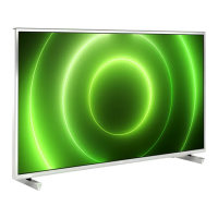
| Screen Size | 32 inches |
|---|---|
| Display Resolution | 1366 x 768 pixels |
| Display Technology | LED |
| HD Type | HD Ready |
| Smart TV | No |
| HDMI Ports | 3 |
| USB Ports | 2 |
| Weight | 6.5 kg |
| Refresh Rate | 50 Hz |
| Viewing Angle | 178 degrees |
| Response Time | 8 ms |
| VGA Port | Yes |
| Headphone Jack | Yes |
| Energy Class | A+ |
| Screen Shape | Flat |
| Internet TV | No |
| Digital signal format system | DVB-T/C |
Details on technical specifications of the TV models, including diversity in described model numbers.
Overview and details of rear and side connections for the TV, including HDMI, USB, SCART, etc.
Essential safety regulations and precautions to be followed during and after repair.
Important warnings regarding electrostatic discharge (ESD), high voltage, and component replacement.
Step-by-step instructions for removing the rear cover, keyboard, SSB, and PSU for specific models.
Detailed procedure for disassembling and removing components like rear cover, Ambilight, and SSB.
Instructions for removing the stand, rear cover, and other components for 65" models.
Overview of service modes including SDM, SAM, Factory, CSM, and ComPair for repair and alignment.
Introduction and specifications for ComPair, a service tool for Philips Consumer Electronics products.
Procedure for upgrading TV software via USB, including preparation and update steps.
Explanation of error codes and how to read the error buffer via SAM, SDM, or CSM.
Procedure for diagnosing errors using the front LED blinking patterns.
General tips for fault finding, NVM editor usage, and troubleshooting common issues like no picture.
Conditions and precautions for performing electrical alignments, including power supply and test probes.
Instructions for performing software alignments like RGB Alignment and White Tone Alignment in SAM mode.
Information on option codes and how to check or change them to ensure correct IC communication.
Procedure for resetting the NVM on a repaired SSB, including loading MAC address and HDCP keys.
Description of the power architecture, power supply units, and output voltages to the chassis.
Circuit diagram and PWB layout for the A 715G6934 Power Supply Unit.
Circuit diagrams and PWB layouts for the A 715G6679 PSU, including AC input and PFC sections.




 Loading...