Do you have a question about the Philips 32PFS6402/12 and is the answer not in the manual?
Details about the TV's operating system and version.
Information on aerial inputs, tuner bands, and video/audio playback standards.
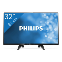
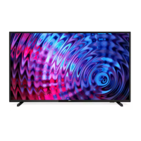
Specifies the diagonal screen size and native resolution of the display.
Lists supported video and computer input resolutions and refresh rates.
Provides physical dimensions and weight for different TV models.
Details the available input/output ports and connectivity options.
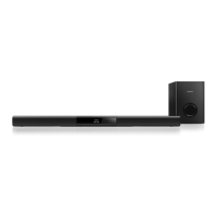
Outlines sound features like WOOX, HD Stereo, and output power.
Covers supported multimedia formats, codecs, and file systems.
Illustrates the routing and management of internal cables within the TV.
Provides detailed steps for disassembling the TV and removing components.
Introduces different service modes like SAM, Factory, and Customer Service modes.
Explains the purpose, specifications, and activation of the Service Alignment Mode.
Details the purpose and activation of the Factory Mode for advanced alignments.
Describes the Customer Service Mode for accessing diagnostic information.
Presents an overview of the CSM interface and its items.
Guides on updating the TV's software using USB drives.
Explains error code interpretation, buffer reading, and clearing procedures.
Instructions for resetting or changing the Panel Code.
Overview of the QM17.4E LA chassis and its key components.
Lists the key components and their specifications for the chassis.
Visual representation of the chassis's main functional blocks and interconnections.
Details the power architecture and unit descriptions of the TV.
Explains the function and voltage outputs of the on-board DC/DC converters.
Describes the front-end circuitry for various broadcast reception standards.
Details the HDMI ports and their configurations for input signals.
Focuses on the main processor and its video/audio processing capabilities.
Provides the block diagram and pinout for the main processor.
Presents the block diagram and pinout for the RT7299BHGQW IC.
Details the block diagram and pinout for the RT8079GQW IC.
Shows the block diagram and pinout for the TAS5760LDDCAR audio amplifier.
Provides the block diagram and pinout for the Si2168-C50-GMR IC.
Detailed schematic for the Power Supply Unit (PSU) circuit.
System power schematics for the main board components.
Circuit diagrams for the IR receiver, LED driver, and 3D functions.
Schematics for the joystick and ambient light key interface.
Exploded view and parts list for the 32" 6402 series TV.
| Screen Size | 32 inches |
|---|---|
| Display Technology | LED |
| Smart TV | Yes |
| HDR | No |
| Operating System | SAPHI |
| HDMI Ports | 3 |
| USB Ports | 2 |
| Digital TV | DVB-T/T2/T2-HD/C/S/S2 |
| Audio Output Power (RMS) | 16 W |
| Refresh Rate | 60 Hz |
| Built-in Wi-Fi | Yes |
| Energy Efficiency Class | A+ |
| Resolution | Full HD (1920 x 1080) |