Mechanical Instructions
EN 19TPM15.3HE LA 4.
2015-Otc-09
back to
div.table
4.2 Service Positions
For easy servicing of a TV set, the set should be put face down
on a soft flat surface, foam buffers or other specific workshop
tools. Ensure that a stable situation is created to perform
measurements and alignments. When using foam bars take
care that these always support the cabinet and never only the
display. Caution: Failure to follow these guidelines can
seriously damage the display!
Ensure that ESD safe measures are taken.
4.3 Assembly/Panel Removal (for 19" 4010W )
Instructions below apply to the 19HFL4010W/12.
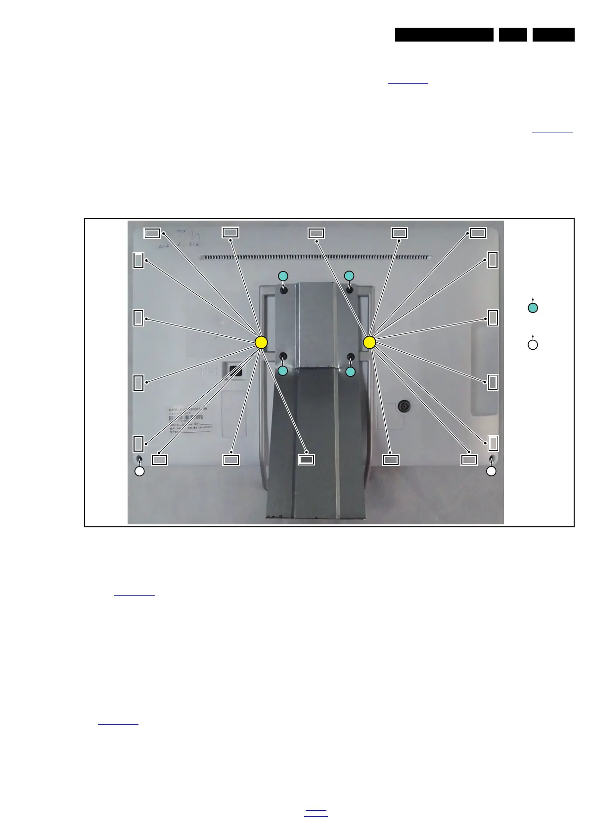
4.3.1 Rear cover
Refer to Figure 4-12
for details.
Warning: Disconnect the power adapter before removing the
rear cover.
1. Remove fixation screws [1] that secure the Stand assy, pull
out the Stand assy from the set. Then remove the fixation
screws [2] that secure the rear cover. Refer to Figure 4-12
for details.
2. At the indicated areas [3] of rear cover is secured by clips.
Be very careful with releasing those.
3. Gently lift the rear cover from the TV. Make sure that wires
and cables are not damaged while lifting the rear cover
from the set.
Figure 4-12 Rear cover removal
4.3.2 Small Signal Board (SSB)
Refer to Figure 4-13
for details.
Caution: it is mandatory to remount all different screws at their
original position during re-assembly. Failure to do so may result
in damaging the SSB.
1. Remove the fixation screw [1] that secure the wall mount
bracket and take out the bracket.
2. Release the clips from the LVDS connector [2] that connect
with the SSB.
Caution: be careful, as these are very fragile connectors!
3. Unplug all other connectors [3] and FFC connector [4].
4. Remove all the fixation screws [5] from the SSB.
5. The SSB can now be shifted from side connector cover,
then lifted and taken out of the I/O bracket. Refer to
Figure 4-13
for details.
19823_101.eps
33
1
M4 × 16
Q3 × 6
1
1
2
2
2
1
1
 Loading...