Mechanical Instructions
EN 21TPM15.3HE LA 4.
2015-Otc-09
back to
div.table
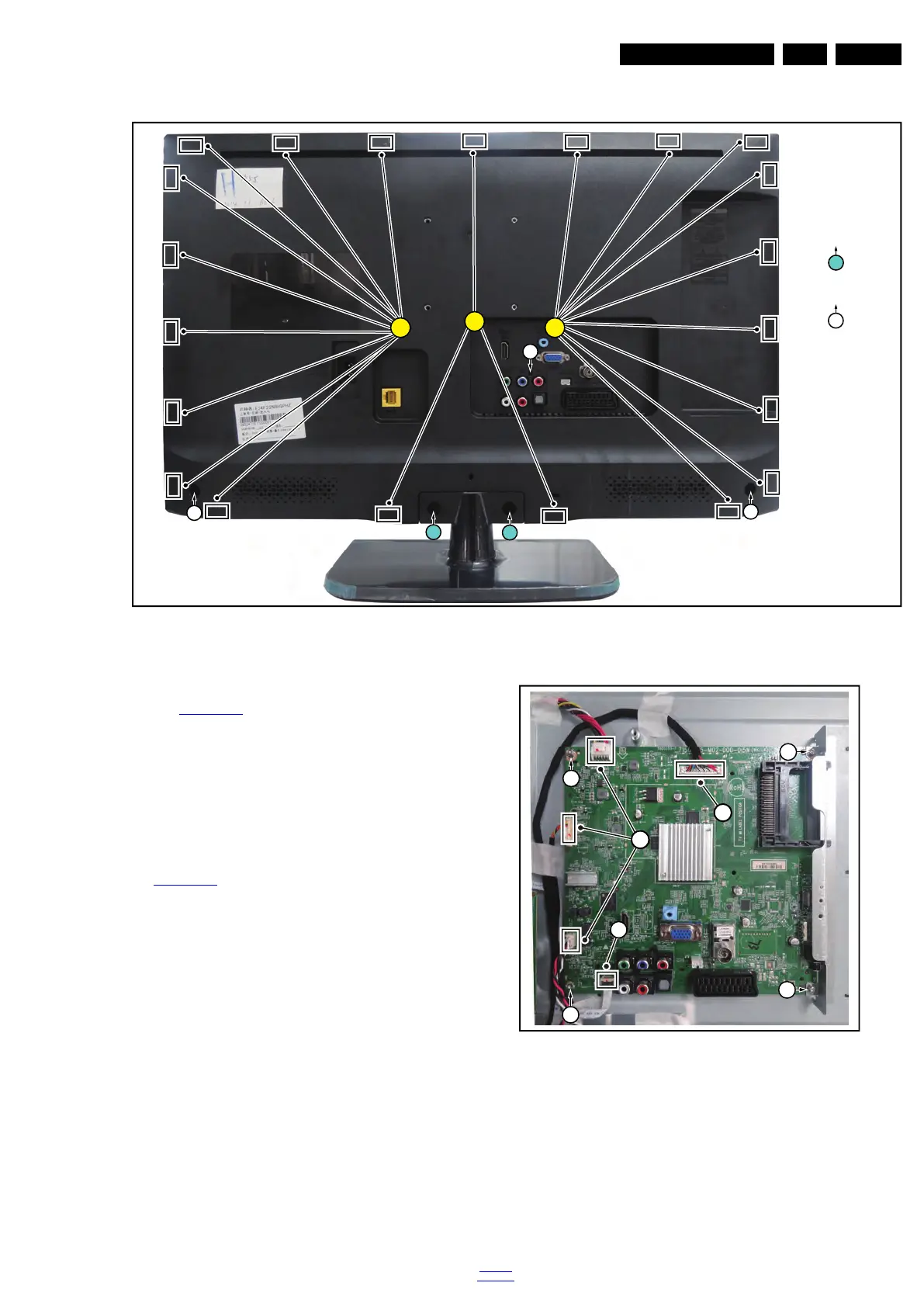
Figure 4-15 Rear cover removal
4.4.2 Small Signal Board (SSB)
Refer to Figure 4-16
for details.
Caution: it is mandatory to remount all different screws at their
original position during re-assembly. Failure to do so may result
in damaging the SSB.
1. Release the clips from the LVDS connector that connect
with the SSB [1].
Caution: be careful, as these are very fragile connectors!
2. Unplug all other connectors [2] and FFC connector [3].
3. Remove all the fixation screws from the SSB [4].
4. The SSB can now be shifted from side connector cover,
then lifted and taken out of the I/O bracket. Refer to
Figure 4-16
for details.
Figure 4-16 SSB removal
4.4.3 Power Supply Unit (PSU)
Caution: it is mandatory to remount all different screws at their
original position during re-assembly. Failure to do so may result
in damaging the PSU.
1. Gently unplug all connectors from the PSU.
2. Remove all fixation screws from the PSU.
3. The PSU can be taken out of the set now.
19820_108.eps
3
3
3
1
Q4 × 25
Q3 × 8
1
1
2
2
2
2
 Loading...