Do you have a question about the Philips 49HFL7011T/12 and is the answer not in the manual?
Provides technical details, specifications, and connection information for the TV set.
Instructions for using the TV, downloadable from Philips websites.
Details rear and side connectors, including pin assignments and specifications.
Refers to block diagrams for PWB/CBA locations.
Essential safety regulations and procedures to follow during TV repair.
Important warnings regarding electrostatic discharge (ESD) and high voltage.
General and schematic notes for measurements, waveforms, and component values.
List of abbreviations used in the manual with their meanings.
Illustrates cable routing for different series, aiding in assembly and disassembly.
Guidelines for safely placing the TV set face down for measurements and alignments.
Step-by-step instructions for removing the stand and rear cover of the TV.
Instructions for re-assembling the TV set, emphasizing correct cable placement and EMC foams.
Overview of service modes like SAM, Factory, and CSM for alignment and diagnosis.
Diagram illustrating the TV set's start-up sequence and operational states.
Mentions ComPair Tool's role as a level shifter, though no longer supported.
Detailed steps for downloading and updating the TV's main software via USB.
Information on error codes, how to read the error buffer, and their meaning.
Method to diagnose errors using front LED blinking patterns when the OSD is not available.
Guidance on troubleshooting common issues like no picture, unstable HDMI, or startup failures.
Specifies conditions for performing electrical adjustments, including power supply and warm-up time.
Indicates that hardware alignments are not applicable for this chassis.
Details how to perform software alignments like White Point and Display Adjustment in SAM mode.
Explains how option codes are used for micro-processor communication and digital diagnosis.
Procedures for resetting the NVM on a repaired SSB and reloading MAC addresses.
Provides information on identifying SSB boards using their "715" code and its components.
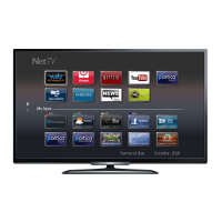
Introduces the new chassis launched in Europe, covering MT5593U and key features.
Describes the power supply unit architecture, control signals, and output voltages.
Details the on-board DC/DC converters and the voltages they deliver to various parts.
Explains the front-end components for analogue tuner and DVB reception.
Details the HDMI input configuration, supported standards, and connector functions.
Describes the main audio and video processor, MT5593UGIJ, and its features.
Shows the internal block diagram of the SOC-EMMC, MT5593UGIJ IC.
Provides the internal block diagram and pin configuration for the FE-TUNER-DEMOD-TPV IC.
Details the internal block diagram and pin configuration for the AOZ1360DIL DC/DC converter IC.
Shows the internal block diagram and pin configuration for the G5318RE1D DC/DC system power IC.
Presents the internal block diagram and pin configuration for the RT8079GQW DC/DC system power IC.
Displays the internal block diagram and pin configuration for the TAS5760LDDCAR audio amplifier IC.
Provides the internal block diagram and pin configuration for the Si21692-C50 FE-TUNER-DEMOD-TPV IC.
Shows the internal block diagram and pin configuration for the RT8079GQW DC/DC system power IC.
Presents a block diagram illustrating the series architecture of the TV, showing component interactions.
Circuit diagram for the A 715G7720 Power Supply Unit, AC input section.
Circuit diagram for the A 715G7831 Power Supply Unit, AC input section.
Circuit diagram for the B 715G8000 Small Signal Board (SSB), including SOC-EMMC.
Circuit diagram for the J 715G7788 IR/LED Panel, including light sensor.
Circuit diagram for the E 715G7872 Keyboard control panel, including joystick and AMBI LIGHT connections.
Circuit diagram for the E 715G7065 Keyboard control panel, including joystick and AMBI LIGHT connections.
Circuit diagram for the AL 715G7789 LED board, showing LOGO lighting.
Circuit diagram for the AL 715G6981 Ambilight Board, detailing TCL5971 functionality.
Circuit diagram for the AL 715G7007 Ambilight Board, detailing TCL5971 functionality.
Circuit diagram for the AL 715G7004 Ambilight Board, showing 8-LED configuration.
Circuit diagram for the AL 715G7865 Ambilight Board, showing 8-LED configuration.
Circuit diagram for the AL 715G7008 Ambilight Board, showing TCL5971 functionality.
Circuit diagram for the AL 715G7004 Ambilight Board, showing 6-LED configuration.
Circuit diagram for the AL 715G7008 Ambilight Board, showing TCL5971_2 functionality.
Circuit diagram for the AL 715G7008 Ambilight 6-LED board.
Circuit diagram for the AL 715G7008 Ambilight 7-LED board.
Shows the physical layout of the Ambilight board for top and bottom sides.
Circuit diagram for the AL 715G7004 Ambilight Board, showing 9-LED configuration.
Circuit diagram for the AL 715G7007 Ambilight Board, showing 8-LED configuration.
Circuit diagram for the AL 715G7008 Ambilight Board, showing 7-LED configuration.
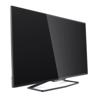
Exploded view and parts list for the 49" 7011 series TV styling.
Exploded view and parts list for the 55" 7011 series TV styling.
Exploded view and parts list for the 65" 7011 series TV styling.
| Screen Size | 49 inches |
|---|---|
| Display Technology | LCD |
| Smart TV | Yes |
| HDMI Ports | 4 |
| USB Ports | 2 |
| Operating System | Android |
| Built-in Wi-Fi | Yes |
| Energy Efficiency Class | A+ |
| Display resolution | 3840 x 2160 pixels |
| Screen shape | Flat |
| Aspect ratio | 16:9 |
| Response time | 6.5 ms |
| Contrast ratio (typical) | 4000:1 |
| Dynamic contrast ratio marketing name | Mega Contrast |
| Display brightness | 350 cd/m² |
| Viewing angle, horizontal | 178° |
| Viewing angle, vertical | 178° |
| 3D | No |
| Built-in speaker(s) | Yes |
| Number of speakers | 2 |
| RMS rated power | 20 W |
| Ethernet LAN | Yes |
| VESA mounting | Yes |
| VESA mounting interfaces | 200 x 200 mm |
| Product colour | Black |
| HDMI ports quantity | 4 |
| USB 2.0 ports quantity | 2 |
| Component video (YPbPr/YCbCr) in | 1 |
| Ethernet LAN (RJ-45) ports | 1 |
| Common interface (CI) | Yes |
| Common interface Plus (CI+) | Yes |
| Audio Return Channel (ARC) | Yes |
| Digital audio optical out | 1 |
| Headphone outputs | 1 |
| HDMI version | 2.0 |
| Depth (with stand) | 270 mm |
| Refresh Rate | 60 Hz |
| Display diagonal | 49 inches |
| Width | 109.8 cm |
| Width (with stand) | 109.8 cm |
| Resolution | 3840 x 2160 (Ultra HD) |