EasyManua.ls Logo

Philips AZ 5130 User Manual

Philips AZ 5130
31 pages
To Next Page IconTo Next Page
Page #1 background imageLoading...
Page #1 background image
Handling Chip Components and Safety ..........................1 - 1
Technical Specification & Service tools...........................2 - 1
Service Measurement......................................................2 - 2
Connections and controls.....................................3 - 1 to 3- 2
Instructions for Use .............................................3 - 3 to 3 - 8
Disassembly Diagram......................................................4 - 1
Pin-description of ICs ..........................................4 - 2 to 4 - 5
Block Diagram .................................................................5 - 1
Wiring Diagram................................................................6 - 1
Tuner And Power Amplifier Board
Circuit Diagram........................................................7 - 1
Layout Diagram.......................................................7 - 2
Radio Alignment ......................................................7 - 2
VCD Board And LCD Board
Circuit Diagram .......................................................8 - 1
Layout Diagram(LCD Board) ..................................8 - 2
Layout Diagram(VCD Board) .......................8 - 3 to 8-4
Tape Board
Circuit Diagram........................................................9 - 1
Layout Diagram.......................................................9 - 2
Exploded Views Diagram
Cabinet ..............................................................10 - 1
Tape Deck .........................................................10 - 2
Mechanical Partslist.......................................................10 - 2
Electrical Partslist............................................11 - 1 to 11 - 2
© 3140 785 32650
Published by LX 0333Service Audio Printed in The Netherlands Subject to modification
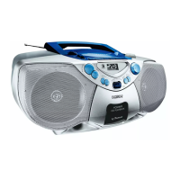
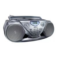
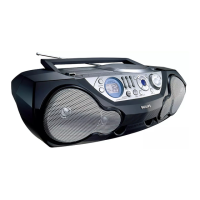
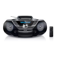
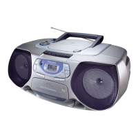
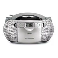
VCD MP3 CD Soundmachine
CLASS 1
LASER PRODUCT
AZ 5130
all versions
TABLE OF CONTENTS
©
Copyright 2001 Philips Consumer Electronics B.V. Eindhoven, The Netherlands
All rights reserved. No part of this publication may be reproduced, stored in a retrieval
system or transmitted, in any form or by any means, electronic, mechanical, photocopying,
or otherwise without the prior permission of Philips.
VIDEO CD
Question and Answer IconNeed help?

Do you have a question about the Philips AZ 5130 and is the answer not in the manual?

Philips AZ 5130 Specifications

General IconGeneral
BrandPhilips
ModelAZ 5130
CategoryPortable Stereo System
Playable Disk TypesCD, CD-R, CD-RW
Display TypeLCD
CD PlayerYes
Cassette PlayerYes
RadioYes
Tuner BandsFM
Connectivity3.5 mm audio input
Power SourceBattery

Summary

Handling Chip Components and Safety

ESD Precautions

Warnings and procedures for electrostatic discharge protection.

General Safety and Laser Warning

Safety regulations, laser product, and leakage current checks.

Technical Specifications

General and Amplifier Specs

Power, impedance, voltage, and frequency details.

Tuner and Cassette Specs

FM/MW tuner and tape deck specifications.

Service Measurement Procedures

SW Tuner Measurement Setup

Diagram for SW tuner testing and setup.

AM Tuner Measurement Setup

Diagram for AM tuner testing and setup.

CD Measurement Setup

Diagram for CD player testing and setup.

Power Supply and Remote Control Details

Power Supply Information

AC and battery power usage and notes.

General Operation and Usage

CD/VCD/MP3-CD Playback Features

Cassette Operations

Cassette Recording Procedures

General recording guidelines and precautions.

Maintenance, Care, and Troubleshooting

General Unit Maintenance and Care

Cleaning and care instructions.

CD Player and Disc Handling

Proper handling of CDs and player.

Tape Deck Maintenance

Cleaning tape deck parts.

Troubleshooting Common Issues

Problem resolution guide.

IC Pin Descriptions - S1A902X01 and General

S1A902X01 Pinout and Description

Pin configuration and voltage details for S1A902X01.

IC Pin Descriptions - Continued

S1A902X01 Pin Descriptions

Continuation of S1A902X01 pin details.

IC Block Diagrams and Pinouts - SPCA711A

SPCA711A Block Diagram and Pinout

Block diagram and pinout for SPCA711A.

IC Block Diagrams and Pinouts - SPCA718A

SPCA718A Block Diagram and Pinout

Block diagram and pinout for SPCA718A.

Tuner and Power Amplifier Board Circuit Diagram

Related product manuals