Service modes, repair tips and faultfinding trees
GB 27CDR 3rd gen. 5.
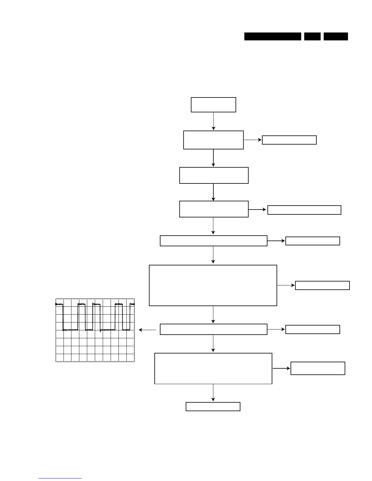
Figure 5-17
NOK
OK
OK
SLEDGE SERVO OK
Switch on player
in MDD mode
SERVO DRIVERS CHECK
USE CDR MAIN BOARD CIRCUIT DIAGRAMS 3 AND 4 AND CDR MAIN BOARD BOTTOM VIEW : SERVO DRIVERS TESTPOINTS
Execute "sledge inwards"
and "sledge outwards" tests
Check power part
Check reset and clock part
Check voltages testpoints S4, S5, S7, S8 : +/- 1.6V
OK
NOK
Check CDM3800
NOK
Check opamp 7225
Check voltage testpoint S1 : if S1=0V then S3=0V
if S1=1V65 then 1V<S3<4V
if S1=3V3 then S3=5V
Check voltage testpoint S2 : if S2=0V then S6=0V
if S2=1V65 then 1V<S6<4V
if S2=3V3 then S6=5V
Check
S1V65
(=1V65) at
testpoint S9
OK
NOK
Check IC7215, T7201, T7202
OK
Check
VSL
signal at testpoint S10
NOK
Check MACE 7270
OK
PM3392A
CH1:1.00 V= MTB 500ns
VSL
GND
Check
SL+
signal at testpoint S11 :
+3V (going to 5V4 when executing "sledge outwards")
Check
SL-
signal at testpoint S12 :
+5V4 (going to 3V4 when executing "sledge outwards")
NOK
Check driver 7240
Check MACE 7270
OK
SLEDGE SERVO OK
SLEDGE SERVO
CL06532018_019.eps
290200