Do you have a question about the Philips CDR880 and is the answer not in the manual?
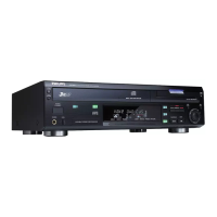
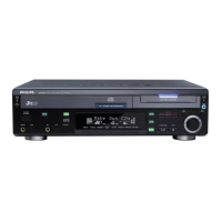
Lists mechanical part differences between CDR880 and CDR870.
Mentions CDR module differences and ordering code.
Mentions modified connector board and optical devices.
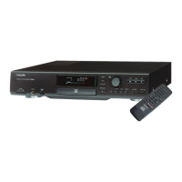
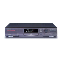
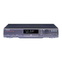
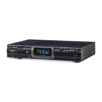
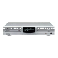
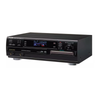
Introduces the CDR870 CD-Recorder and its capabilities.
General specs: mains voltage, frequency, power consumption.
Details line, digital, and optical input/output specs.
Performance details for audio paths.
Specifications for headphone output.
Physical dimensions and weight of the unit.
Specifications for the laser device unit.
Important safety and electrical notes for UK users.
Warning about laser safety and servicing procedures.
Covers unpacking, placement, and power setting.
Identifies controls and connections on the front panel.
Identifies connectors on the rear panel.
Identifies buttons on the remote control.
Explains the meaning of display indicators.
Instructions for connecting audio sources.
Covers battery loading, power on/off, disc handling.
Steps for recording from analogue sources.
Steps for recording from digital sources.
Synchronized recording from digital sources.
Procedure to finalize a recorded disc.
Procedure to erase a CD-RW disc.
How to play discs and use playback controls.
How to set up and play programmed tracks.
Explains various messages displayed by the unit.
Troubleshooting guide for common symptoms.
Information on the Diagnostic Program and its use.
Instructions for cleaning and maintaining the recorder and discs.
Lists general, audio, recording, and playback specs.
General fire and shock hazard precautions for technicians.
Procedures for cold and hot leakage current checks.
Guidelines for replacing safety-critical parts.
Warning regarding laser radiation during service.
General tips, dismounting, mounting, precautions for chip components.
Lists specialized tools for servicing.
Steps to remove the CDR module assembly.
Steps to remove the power supply board.
Steps to remove the front assembly and cover.
Steps to remove various internal boards.
Lists signals and their descriptions.
Continues listing signals and their descriptions.
Flowchart for performing diagnostic tests.
Flowchart for troubleshooting general faults.
Troubleshooting guide specific to CDDA discs.
Troubleshooting guide specific to CD-R discs.
Troubleshooting guide specific to CD-RW discs.
Measures voltage supplies at the display PCB.
Checks the frequency of the display controller oscillator.
Checks display controller input/output lines.
Shows signals on grid and segment control lines.
Shows connections between different boards.
Detailed circuit diagram for the power supply.
Component layout on the power supply board.
Solder layout on the power supply board.
Details transformer voltages and connections for different versions.
Circuit diagram for the headphone section.
Circuit diagram for the level control section.
Component layout for the headphone board.
Component layout for the level board.
Circuit diagram for the display and control functions.
Component layout for the display board.
Schematic diagram of the connector board.
Component layout for the connector board.
More detailed schematic diagram of the connector board.
Lists mechanical parts and their numbers.
Lists types and uses of screws.
Lists components for the power supply board.
Lists general electrical components like switches, holders, etc.
Lists various capacitors used in the unit.
Lists resistors.
Lists filters.
Lists diodes and ICs.
Lists components related to mains voltage.
Lists connection components.
Continuation of resistor listings.
Continuation of diode and IC listings.
Lists resistors on the connector board.
Lists miscellaneous components on the connector board.
Lists capacitors on the connector board.
Lists ICs on the connector board.
Lists mains voltage related components.
Lists connection components.
Introduces the basics of CD-Recordable and CD-ReWritable discs.
Explains CD-R disc technology and characteristics.
Explains CD-RW disc technology and characteristics.
Describes the analogue recording process.
Describes the digital recording process.
Overview of the Philips CD-Recorder features and capabilities.
Explains the CD Sync recording feature.
Explains the Serial Copy Management System.
Describes the process of finalizing a disc.
Lists standard CD playback features.
General specs: system, channels, discs, power.
Audio specs: frequency response, S/N, distortion.
Lists available recording functions.
Lists available playback functions.
Lists included accessories.
Explains the CD-Recording system.
Highlights differences between recordable and pre-recorded CDs.
Outlines requirements for CD-Recording system compatibility.
Describes the structure of CD-R/RW discs.
Provides dimensions of unrecorded and recorded discs.
Details the physical structure of CD-R discs.
Specifies groove dimensions on the disc.
Explains the CD-R writing process.
Explains the CD-RW writing process.
Explains the process of erasing CD-RW discs.
Explains the direct overwrite strategy.
Describes the groove wobble phenomenon.
Explains wobble modulation for time-code.
Requirements for blank CD-Recording discs.
Requirements for recorded CD-Recording discs.
Explains data areas on a CD-R disc.
Details the PCA for optimum recording power.
Explains the PMA for track data.
Describes the Lead In Area contents.
Explains the Program Area for audio tracks.
Defines remaining recordable area and end mark.
Rules for linking successive recordings.
Discusses causes and effects of misrecording.
Provides a simplified block diagram of the recorder.
Overview of the central repair module.
Identifies areas for local component repair.
Details the CD-Recording drive mechanism.
Explains the CDM mechanism components and functions.
Details the 3-spot push pull tracking system.
Discusses shock sensitivity during writing.
Specifies the focus radius requirement.
Discusses disc eccentricity.
Describes the functions of the CDM board.
Covers laser control and optical power calibration.
Explains servo functions and wobble processing.
Explains the normalizing function.
Continuation of servo function details.
Continuation of wobble processing explanation.
Explains the servo microcontroller's role.
Describes the input signal path to the encoder.
Explains digital signal input processing.
Explains analogue to digital conversion.
Details the CIRC EFM encoding process.
Describes the output path with the decoder.
Explains the DAC analogue output.
Explains the digital output.
Explains signal monitoring.
| power supply | AC 230V(/00), 120V(/17), 120/230V(/11) |
|---|---|
| power consumption | 15 W |
| line output voltage | 2 Vrms |
| operating temperature | 5-35 °C |
|---|
| frequency response | 20 Hz-20 kHz |
|---|---|
| playback S/N | 105 dB |
| playback dynamic range | 98 dB |
| playback total harmonic distortion | 85 dB |
| recording S/N | 90 dB |
| recording dynamic range | 95 dB |
| recording total harmonic distortion | 85 dB |
| digital coaxial output | 0.5 V(pp)/75Ω |
| digital optical output | -20 dBm |
| headphones | 0-5 Vrms/8-2000Ω |
| digital coaxial input | 32-48 kHz |
| digital optical input | 32-48 kHz |
| analogue input | 700 mVrms/50kΩ |
| weight | 4 kg |
|---|---|
| width | 435 mm |
| depth | 310 mm |
| height | 75 mm |