Mechanical instructions
GB 7CDR 3rd gen. 4.
4. Mechanical instructions
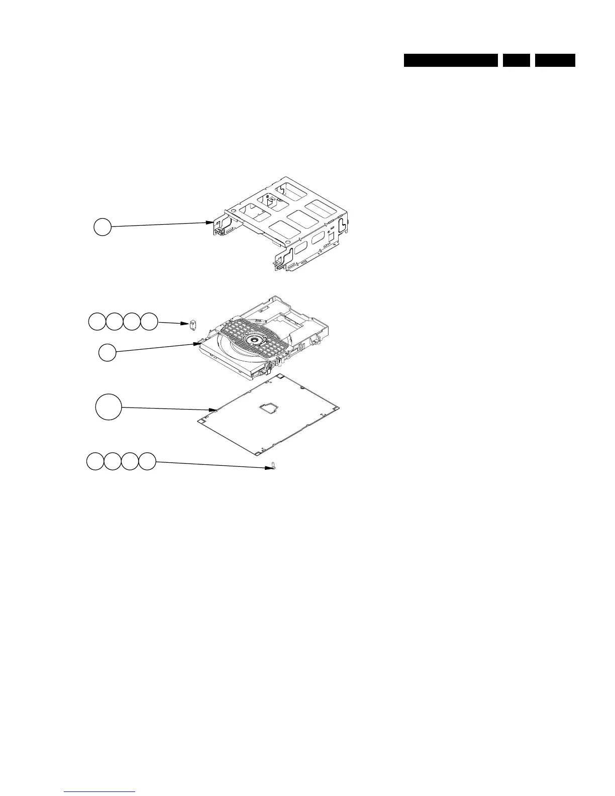
4.1 Loader CDL4009
CDL4009 consists of metal loader bracket item 82 and glued
on it an identification sticker (on which the module production
number and production code is printed); 4 suspension rubbers
items 76, 77, 78 and 79 which carry loader assembly item 81;
and on the bottom side the CDR mainboard 1001 is mounted.
Notice that mainboard is dependant to the applied set and has
to be adjusted to mounted CDM in loader in case of exchange.
See next figure, Loader CDL4009
Figure 4-1
To demount loader module CDL4009:
1. Mainboard item 1001. Beware of connections to CDM.
Optical pick-up unit has to be ESD protected!
2. Loosen suspensions 76, 77, 78 and 79 from metal loader
bracket 81
3. Take out Loader assy CDL
MAIN BOARD CDR
M3 X 6
LOADER ASSY CDL
SUSPENSION
LOADER BRACKET
82
76
77 78 79
81
1001
97
98 99
100
82: LOADER BRACKET 3104 121 23900
81: LOADER ASSY CDL 9305 043 20900
76: SUSPENSION 3104 144 05730
CL06532018_001.eps
090300