Faultfinding Guide
GB 64 CDR7758.
Measurements
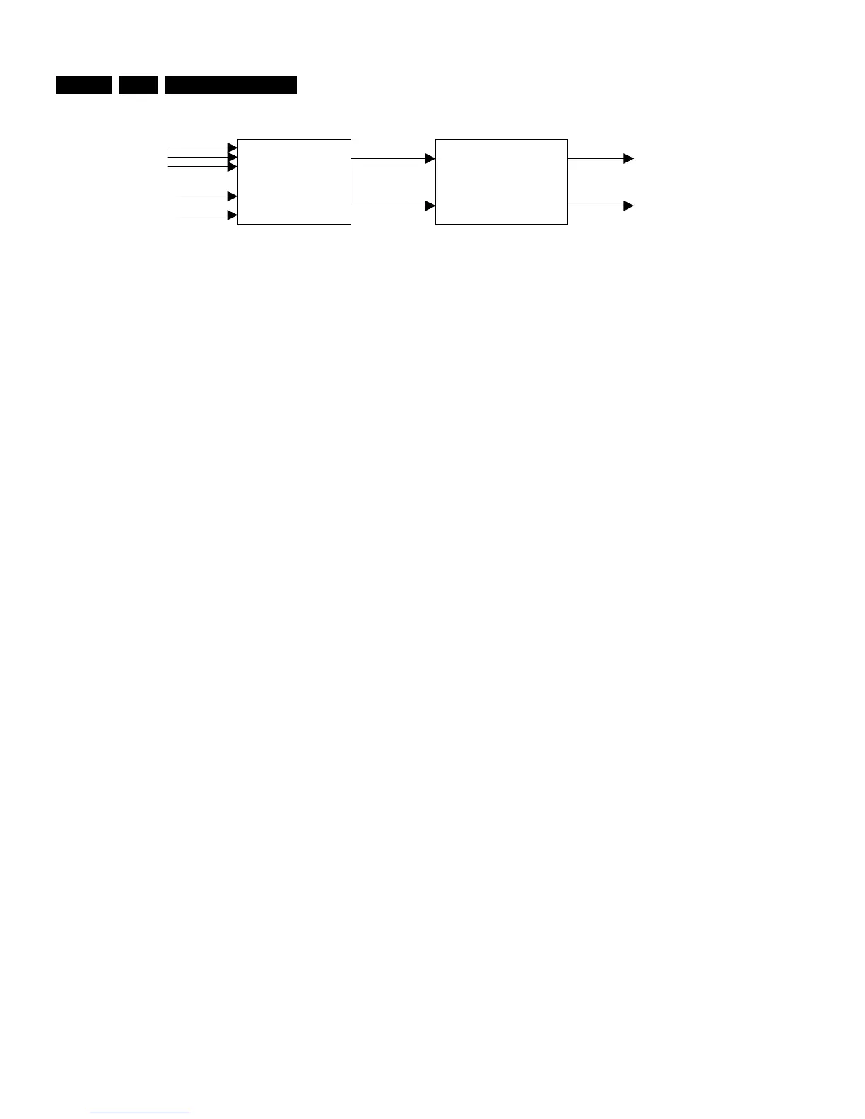
Figure 8-33
Keep processor 7202 in reset by forcing pin 7 of connector
1208 to +5V. This puts the processor outputs in tristate. Check
the reset at pin 4 of processor 7202 to make sure that the
processor is in reset.
Now, force port 0-4 pin 33 at 7202 to 0V to set the decoder
outputs (SCLK, WCLK, DATA, and CL11).
Check the MUTE pin 11 at 7309 : this pin should be low.
Connect via an I2S generator I2S-signals to the DAC :
Pin 1 at 7309: SLCK.
Pin 2 at 7309: WCLK.
Pin 3 at 7309: DATA.
Connect also the SYSCLK pin 6 at position 7309 to a clock
signal of 11.2896 MHz ( 100ppm.
Generate an I2S signal equivalent with a sine wave of 1kHz at
0dB for both left and right channels.
Check if 0.8 VRMS at pins 14 and 16 at location 7209 with a
DC of 1.65VDC.
Check if 1.7 VRMS ( 2 dB at connector pins 1and 3 at location
1209.
Force MUTE Pin 11 at 7309 high.
Measure again at pins 1 and 3 at location 1209 : both signals
should be at -90 dB.
DAC AMPLIFIER
IIS
CLK11
NMUTE
22
25
1200 - 17
1200 - 19
CL96532086_062.eps
080999