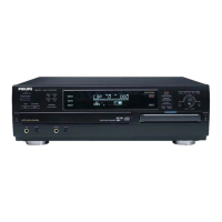
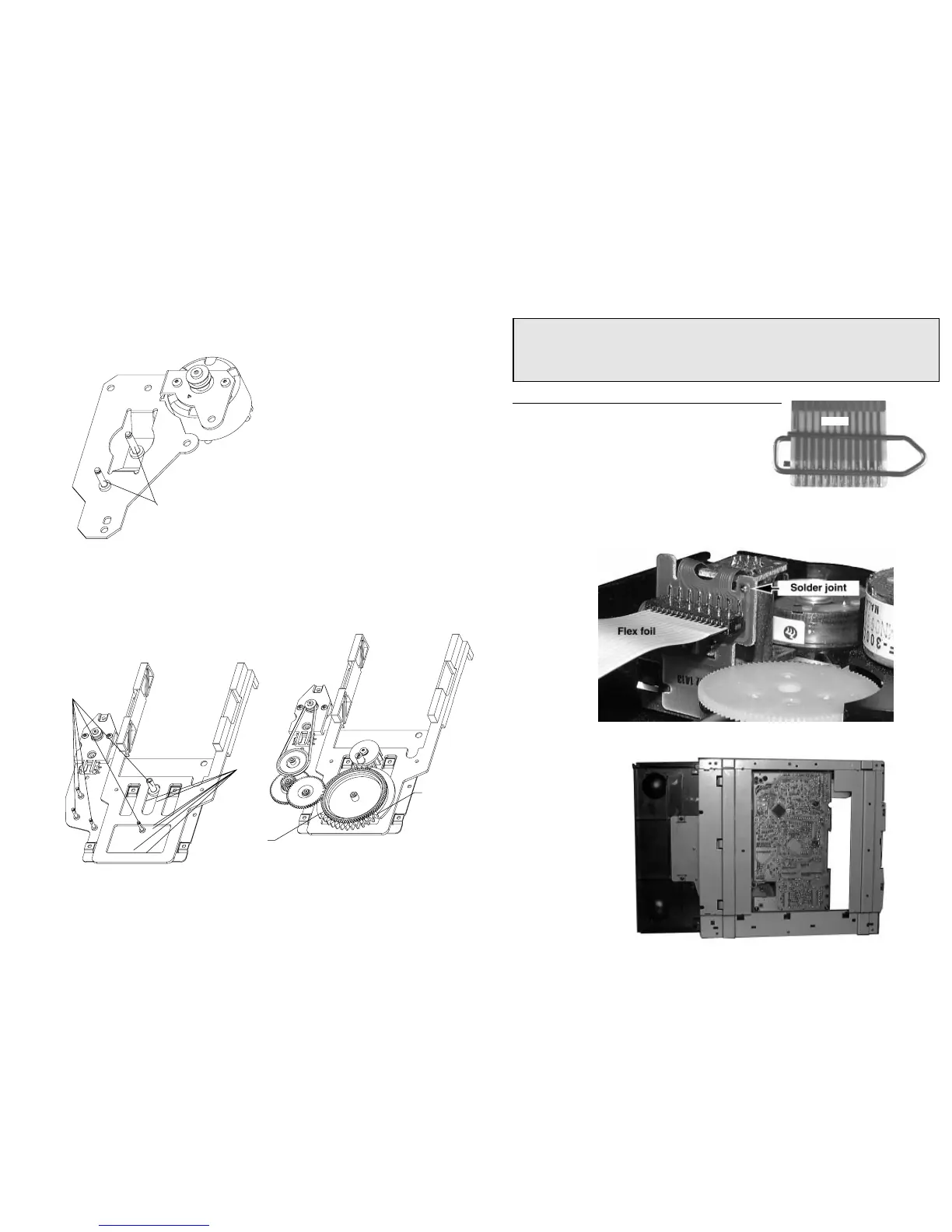
Use only grease Polylub GLY 801 service codenumber 4822 390 10136
Service Position
The following steps have to be done when replacing the CD mechanism:
1. Disconnect flexfoil cable from old CD drive
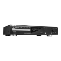
2. Put a paper clip onto the flexfoil cable to short-circuit connections (fig.1)
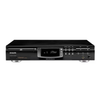
3. Remove old CD drive
4. Remove paper clip from flexfoil cable
5. Connect flexfoil cable to new CD drive
6. Position new CD drive on its studs
7. Remove soldered short-circuit from Laserunit (see below)
CHARGED CAPACITORS ON THE SERVO BOARD MAY DAMAGE THE CD DRIVE ELECTRONICS WHEN
CONNECTING A NEW CD MECHANISM. THAT´S WHY, BESIDES THE SAFETY MEASURES LIKE
• SWITCH OFF POWER SUPPLY
• ESD PROTECTION
ADDITIONAL ACTIONS MUST BE TAKEN BY THE REPAIR TECHNICIAN.
WARNING
fig.1
Attention: The laser diode of this CD drive is protected against ESD by a solder joint which shortcircuits the laser
diode to ground.
For proper functionality of the CD drive this solder joint must be removed after connecting the drive to
the set.
Lubrication Instructions