EasyManua.ls Logo

Philips CDR785/00 User Manual

Philips CDR785/00
67 pages
To Next Page IconTo Next Page
Page #1 background imageLoading...
Page #1 background image
chapter
Technical Specification and Measurement setup................1-1, 1-2
Location of printed circuit boards............................................1-3
Warnings & Safety..................................................................2-1
Brief Operating Instructions ..............................................3-1 to 3-15
Dismantling Instructions.....................................................4-1 to 4-5
Service hints ......................................................................5-1 to 5-3
Service Test Program........................................................5-4 to 5-6
BLOCK DIAGRAMS ..........................................................6-1 to 6-5
WIRING DIAGRAM.................................................................6-6
POWER BOARD (for orientation only) ..............................7-1 to 7-4
FRONT BOARD.................................................................7-5 to 7-6
KEY BOARD left.....................................................................7-7
KEY BOARD right...................................................................7-8
chapter
HEADPHONE/MICROPHONE BOARD ...........................7-9 to 7-10
INTERFACE BOARD......................................................7-11 to 7-13
3CDC MODULE................................................................8-1 to 8-9
EXPLODED VIEWS
apparatus..........................................................................10-1
3CDC module ...............................................................8-8 to 8-9
MECHANICAL PARTSLIST see Exploded views
ELECTRICAL PARTSLIST...................................................10-2 ff
CDR785/00/01C/17
Published by MS 0012 Service Audio Printed in The Netherlands Subject to modification
© 3103 785 25030
Compact Disc Recorder
C
D
T
E
X
T
E
D
I
T
IN
G
CD 1
CD 2
C
D 3
CDR
AUX
C
D
C
D
C
O
M
P
I
L
E
C
D
R
E
C
O
R
D
JOG CONTROL
NO
YES
R
E
C
T
Y
P
E
E
R
A
S
E
F
I
N
A
L
I
Z
E
R
E
C
L
E
V
E
L
B
A
L
A
N
C
E
T
E
X
T
P
R
O
G
T
R
A
C
K
E
D
I
T
O
P
E
N
/C
L
O
S
E
O
P
E
N
/
C
L
O
S
E
M
I
C
P
H
O
N
E
S
O
N
/
O
F
F
R
E
P
E
A
T
C
D
T
E
X
T
S
H
U
F
F
L
E
D
I
S
P
L
A
Y
C
D
-
C
H
A
N
G
E
A
U
D
I
O
C
D
R
E
C
O
R
D
E
R
C
D
R
7
8
5
CD R
EC
O
RD
ER
A
U
T
O
L
E
V
E
L
C
O
N
T
R
O
L
CD 1
C
D
2
CD
3
CDR
A
UX
C
D
C
D
C
O
M
P
I
L
E
C
D
R
E
C
O
R
D
JOG
CONTROL
NO
YES
R
E
C
T
Y
P
E
E
R
A
S
E
F
I
N
A
L
I
Z
E
R
E
C
L
E
V
E
L
B
A
L
A
N
C
E
T
E
X
T
P
R
O
G
T
R
A
C
K
E
D
I
T
O
P
E
N
/
C
L
O
S
E
O
P
E
N
/
C
L
O
S
E
M
I
C
P
H
O
N
E
S
O
N
/
O
F
F
R
E
P
E
A
T
C
D
T
E
X
T
S
H
U
F
F
L
E
D
I
S
P
L
A
Y
C
D
-
C
H
A
N
G
E
A
U
D
I
O
C
D
R
E
C
O
R
D
E
R
C
D
R
7
8
5
CD RE
COR
DER
A
U
T
O
L
E
V
E
L
C
O
N
T
R
O
L
T
EX
T
TOT
AL
T
R
ACK
TIME TO
TAL
R
EM
STEP
DIGITAL
C
D
RW
C
D
RW
C
O
M
P
I
L
E
D
I
S
C
A
L
L
P
R
O
G
R
A
M
R
E
C
O
R
D
I
N
P
R
O
G
R
E
S
S
S
H
U
F
F
L
E
R
E
P
E
A
T
T
R
A
C
K
E
D
I
T
R
EC TRAC
K
T
IM
E
1
2
3456 78
9
1
0
1
1
1
2
1
3
1
4
1
5
1
6
1
7
1
8
1
9
2
0
+
12
O
PTIC
AL
12
ANA
LOG
FI
NA
LI
ZE
ALC
T
EX
T
TOT
AL
T
R
ACK
TIME TO
TAL
R
EM
STEP
DIGITAL
C
D
RW
C
D
RW
C
O
M
P
I
L
E
D
I
S
C
A
L
L
P
R
O
G
R
A
M
R
E
C
O
R
D
I
N
P
R
O
G
R
E
S
S
S
H
U
F
F
L
E
R
E
P
E
A
T
T
R
A
C
K
E
D
I
T
R
EC TRAC
K
T
IM
E
1
2
3456 78
9
1
0
1
1
1
2
1
3
1
4
1
5
1
6
1
7
1
8
1
9
2
0
+
12
O
PTIC
AL
12
ANA
LOG
FI
NA
LI
ZE
ALC
TEXT T
OT
A
L
TRAC
K
TIME TO
TAL
REM
S
TEP
DIG
ITAL
C
D
RW
C
D
RW
C
O
M
P
I
L
E
D
I
S
C
A
L
L
P
R
O
G
R
A
M
R
E
C
O
R
D
I
N
P
R
O
G
R
E
S
S
S
H
U
F
F
L
E
R
E
P
E
A
T
T
R
A
C
K
E
D
I
T
REC T
RA
CK
TIM
E
1
2
3456
7
8
9
1
0
1
1
1
2
1
3
1
4
1
5
1
6
1
7
1
8
1
9
2
0
+
12
O
PT
IC
AL
12
A
NA
LO
G
FINAL
IZE
AL
C
123
456
7
89
0
S
P
A
C
E
U
V
W
M
N
D
E
F
T
R
A
C
K
I
N
C
R
.
P
R
O
G
R
A
M
X
Y
Z
O
P
Q
G
H
I
C
D
T
E
X
T
C
D
3
C
D
R
C
D
2
C
D
1
R
E
P
E
A
T
S
H
U
F
F
L
E
N
OYE
S
T
E
X
T
E
D
I
T
R
S
T
J
K
L
A
B
C
B
R
IG
H
T
N
E
S
S
123
456
78
9
0
S
P
A
C
E
U
V
W
M
N
D
E
F
T
R
A
C
K
IN
C
R
.
P
R
O
G
R
A
M
X
Y
Z
O
P
Q
G
H
I
C
D
T
E
X
T
C
D
3
C
D
R
C
D
2
C
D
1
R
E
P
E
A
T
S
H
U
F
F
L
E
N
OY
E
S
T
E
X
T
E
D
I
T
R
S
T
J
K
L
A
B
C
B
R
IG
H
T
N
E
S
S
S
T
O
P
S
T
O
P
P
L
A
Y
/P
A
U
S
E
P
L
A
Y
/P
A
U
S
E
CLASS 1
LASER PRODUCT
©
Copyright 2000 Philips Consumer Electronics B.V. Eindhoven, The Netherlands
All rights reserved. No part of this publication may be reproduced, stored in a retrieval
system or transmitted, in any form or by any means, electronic, mechanical, photocopying,
or otherwise without the prior permission of Philips.
CDR786/00
TABLE OF CONTENTS
SERVICING
For servicing CDR785/CDR786, the sets can be divided into two parts:
1. Except for the Power board (Switched Mode Power Supply) and the CD-R/W module the set has to
be repaired on component level.
2. The Power board and the CD-R/W module will be exchanged completely in case of a failure.
The defective CD-R/W module has to be returned for central repair.
Available circuit descriptions:
The Basics of Compact Disc Recordable/Rewritable
4822 725 25242
3rd generation Compact Disc Recording
3104 125 40100

Table of Contents

Question and Answer IconNeed help?

Do you have a question about the Philips CDR785/00 and is the answer not in the manual?

Philips CDR785/00 Specifications

General IconGeneral
TypeCD Recorder
Disc FormatsCD, CD-R, CD-RW
Playback FormatsCD-DA
Recording FormatsCD-DA
Frequency Response20 Hz - 20 kHz
Analogue OutputsRCA
Digital InputsCoaxial, Optical
Digital OutputsCoaxial, Optical
Digital-to-Analog ConverterBitstream Conversion
OutputsHeadphones

Summary

Technical Specification

General, Input/Output, Audio Performance

Details general, input/output, and audio performance specifications for the device.

Remote Control and Measurement Setup

Covers remote control commands and the necessary setup for measurements.

Warnings & Safety

ESD Precautions

Explains ESD susceptibility and necessary precautions during repair for sensitive components.

General Safety Regulations

Outlines requirements for restoring the set to original condition and using specified parts.

Laser Safety

Warns about invisible laser radiation when the unit is open and direct exposure to the beam.

General Information

Welcome and Accessories

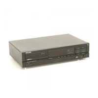
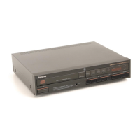
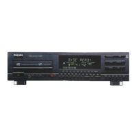
Introduces the product and lists supplied accessories for setup and operation.

Technical Data

Provides general product specifications including dimensions and power consumption.

Controls and Connections

Front Panel Controls

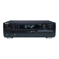
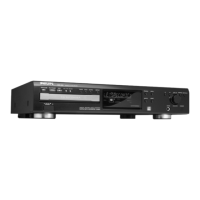
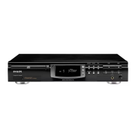
Details the functions of buttons and connectors located on the front of the unit.

Connections at the Back

Explains the purpose of various input and output connectors on the rear of the unit.

Display Indications

Display Messages

Lists and explains various messages shown on the unit's display during operation.

Installation

Connection Types

Covers general, analog, digital coaxial, and optical connection methods.

Power Supply and Setup

Details power requirements and recommendations for placement and ventilation.

Loading Discs

CD Recorder Disc Loading

Instructions for inserting discs into the CD recorder tray.

CD Changer Disc Loading

Procedures for loading discs into the CD changer carousel.

Playing Discs

Playing CDs on the Recorder

Steps for playing discs using the CD recorder.

Playing CDs on the Changer

Instructions for selecting and playing discs from the CD changer.

CD Text Display

How to view and use CD text information during playback.

Selecting Tracks and Discs

Methods for selecting specific tracks or discs during playback or standby.

Programming Functions

Programming Track Numbers

Steps to select and store tracks for playback or recording programs.

Erasing and Clearing Programs

Instructions for removing tracks from a program or clearing the entire program.

Recording Operations

Recording General Information

Basic principles of recording, including sources and disc finalization.

Internal Recording Modes

Details on high-speed and normal speed recording from the internal changer.

External Recording Modes

Procedures for recording from external sources, including synchronized start.

Microphone Recording

Instructions for mixing microphone input or recording solely from it.

Disc (Un)Finalizing and Erasing

Finalizing CDR & CDRW Discs

Steps for finalizing discs for compatibility and protection.

Unfinalizing CDRW Discs

Process for unfinalizing a CDRW to allow further recording or erasing.

Erasing CDRW Discs

Methods for erasing single tracks or the entire content of a CDRW disc.

Special Features

Text Editing

Functionality for adding/editing text for discs and tracks during operation.

Track Editing

How to create custom 'tracks' by marking passages within existing tracks.

Troubleshooting

Common Symptoms and Solutions

Lists issues like no power, no sound, remote errors, and their resolutions.

Dismantling Instructions

Top and Tray Cover Removal

Step-by-step guide to removing the unit's top and tray covers.

Front Cabinet and Module Removal

Procedures for dismantling the front cabinet and the 3CDC module.

Board Dismantling

Instructions for removing the CDC, CDR, and Power boards from the unit.

Service Hints

Service Tools and Chip Handling

Lists required tools and guidelines for safely handling small electronic components.

Board Service Positions

Illustrates how to position various boards for servicing and reconnection.

Service Test Program

Module Specific Tests

Outlines tests for CD-Changer and CDR modules, including electrical and mechanical.

Various System Tests

Describes tests for display, quartz, key input, and rotary encoder functions.

Block Diagrams

Component Board Diagrams

Shows block diagrams for Key, Front, Interface, CDR, Mains, and Headphone boards.

Module Diagrams

Provides block diagrams for 3CDC, CDR modules, and Power Supply.

Wiring Diagram

Power Board Details

Board Layout and Orientation

Shows component/copper views for orientation during servicing.

Front Board Details

Component Layout and Connections

Illustrates component placement and display connection points.

Key Board Details

Key Board Left Layout

Shows component and copper-side views of the left key board.

Key Board Right Layout

Shows component and copper-side views of the right key board.

Headphone/Microphone Board Details

Board Layout Views

Illustrates component and copper-side layouts of the headphone/microphone board.

Interface Board Details

Board Layout Views

Shows component and copper-side layouts of the interface board.

Analog Part Circuitry

Details the analog signal processing and selector sections of the interface board.

3CDC-DS Module Information

Module Dismantling and Service

Provides instructions for dismantling the module and general service advice.

Lubrication and ESD Precautions

Guides on proper lubrication points and ESD safety measures for the module.

Module Block Diagram and Wiring

Presents the module's block diagram and CD drive wiring schematic.

Exploded Views

3CDC Module Views

Illustrates exploded views of the 3CDC module's drawer and chassis.

Apparatus and Mechanical Parts

Shows an exploded view of the entire apparatus and lists mechanical parts.

Electrical Parts Lists

Front Board Parts

Lists all electrical components for the front board, categorized by type.

Key Board Parts

Lists electrical components for the left and right key boards.

Headphone/Microphone Board Parts

Lists electrical components for the headphone/microphone board.

Interface Board Parts

Lists electrical components for the interface board, categorized by type.

3CDC-DS Module Parts

Lists electrical components for the 3CDC-DS module, categorized by type.

Related product manuals