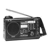
This document describes the Philips D 2999 world receiver, a portable radio designed for comprehensive reception across various frequency bands.
Function Description
The Philips D 2999 is a world receiver capable of tuning into FM, Long Wave (LW), Medium Wave (MW), and Short Wave (SW) broadcasts. It features both manual and automatic tuning options, as well as the ability to store and recall preset stations. The receiver is designed for both stationary and portable use, offering multiple power supply options. A key feature is its Single-Side Band (SSB) modulation capability, which allows for the reception of amateur radio, communication, and weather forecast transmissions that would otherwise be unintelligible on a standard receiver. The device also includes a clock and alarm function, making it a versatile personal device.
Important Technical Specifications
Frequency Coverage:
- Total: 150 - 29999 kHz (for the /02 version up to 26100 kHz) and 87.5 - 108 MHz.
- FM: 87.5 - 108 MHz
- LW: 150 - 360 kHz
- MW: 520 - 1608 kHz
- SW Bands:
- 120 meter: 2300 kHz to 2495 kHz
- 90 meter: 3200 kHz to 3400 kHz
- 60 meter: 4750 kHz to 5060 kHz
- 49 meter: 5950 kHz to 6200 kHz
- 41 meter: 7100 kHz to 7300 kHz
- 31 meter: 9500 kHz to 9900 kHz
- 25 meter: 11650 kHz to 12050 kHz
- 19 meter: 15100 kHz to 15600 kHz
- 16 meter: 17550 kHz to 17900 kHz
- 13 meter: 21450 kHz to 21850 kHz
- 11 meter: 25600 kHz to 26100 kHz
Power Supply:
- Supply Batteries: Six R20, UM-1, or D type batteries for the radio section.
- Memory Batteries: Three R6, UM-3, or AA type batteries.
- Car Battery Supply: 9 - 14 Volts (requires a special power-supply cable).
- Mains Supply: 220/240 Volt and 110/127 Volt (selectable via a plate covering the mains lead socket).
- External Speaker Impedance: 4 ohm.
- Headphone Impedance: 8-16 Ohm.
Standardized Channel Spacing:
- 5 kHz for 2300 kHz - 26100 kHz (all countries).
- 10 kHz on 150 - 1608 kHz for North and South America.
- 9 kHz on 150 - 1608 kHz for all other countries.
Usage Features
Controls and Connections (Refer to Fig. 1):
- Main speaker on/off switch
- Signal strength/battery check button
- Light button
- Main speaker
- External DC supply socket
- Telescopic aerial
- Waverange buttons with LED indicators
- Radio on/off button
- Carrying handle
- Fixing screw for carrying handle
- Preset buttons
- Tuning knob
- Frequency keyboard
- Gain control
- Start/stop button for search facility
- BFO control
- Gain on/off switch
- BFO on/off switch
- Headphone socket
- Local/distant switch
- Narrow/wide bandwidth switch
- Treble control
- Clock/alarm and display function buttons
- Bass control
- LCD display
- Volume control
- Field strength/battery check meter
- Monitoring speaker
- External aerial connections
- Battery compartment for supply batteries
- AM external aerial switch
- FM external aerial switch
- Line out DIN socket
- Line out phono socket
- External loudspeaker socket
- Mains socket
- Mains socket plate
- 12 hr./24 hr. switch
- 9/10 kHz switch
- Battery compartment for memory batteries
Operation:
- Switching On/Off: Use the RADIO ON/OFF button (8).
- Volume and Tone Control: Adjust with VOLUME control (26), TREBLE control (22), and BASS control (24).
- Illumination: The display and meter (25, 27) can be illuminated by pressing the Light button (3). Illumination is continuous when powered by mains or car battery, and automatic shut-off when on battery power.
- Bandwidth Switch (21): Select 'narrow' for interference reduction from adjacent AM stations or 'wide' for better sound quality with strong AM stations.
- Field Strength/Battery Check Meter (27): Check signal strength with switch (2) depressed, or battery condition with switch (2) in the unlocked position.
- Tuning:
- Frequency Keyboard (13): Directly key in desired frequencies. For FM, frequencies are entered in MHz (e.g., 9-8 for 98.0 MHz).
- Tuning Knob (12): Tune within a selected waverange (7) or across all waveranges. Three tuning speeds are available: slow (10 kHz/1 kHz per click), medium (20 kHz/2 kHz per click), and fast (100 kHz/10 kHz per click).
- Automatic Search (15): Searches upwards from the current frequency until a station of sufficient strength is found. The search stops automatically when a station is found or can be manually stopped.
- Waverange Selection (7): Automatically tunes to the lowest frequency in the selected waverange. LED indicators show the active waverange(s).
- Storing Presets (11): Up to sixteen presets (A1-D4) can be stored using the 'STORE PRESET' button on the preselection keyboard (11) followed by the desired letter/figure combination.
- Recalling Presets: Key in the related letter/figure combination from the preselection keyboard (11).
- SSB Reception: Requires setting 'AM GAIN' switch (17) to 'MAN', 'AM GAIN' control (14) to 'MAX', and 'BFO' control (16) to mid-position. The BFO switch (18) must be 'on'. Adjust BFO control (16) for intelligibility.
- Distant/Local Selector Switch (20): Reduces receiver sensitivity for strong local transmitters.
- Clock and Alarm:
- 12/24 Hour Mode (38): Select before inserting memory batteries. AM/PM sign on display (25) confirms 12-hour mode.
- Time Setting: Press 'TIME' button (23), then 'SET' button (23). Enter time using the main keyboard (13).
- Alarm Time Setting: Press 'ALARM' button (23), then 'SET' button (23). Enter alarm time using the main keyboard (13).
- Alarm On/Off: Press 'ALM ON/OFF' button (23). A (((O))) sign on the display (25) indicates the alarm is active. The alarm automatically switches off after 59 minutes if not manually stopped.
- External Connections:
- External Aerials (29, 31, 32): Connect external AM/FM aerials. Switches (31, 32) must be set to 'EXT'.
- Amplifier/Tape Recorder (33, 34): Connect to 'aux' or 'tape' input. Radio loudspeaker remains active unless volume is set to MIN.
- Headphone Socket (19): Connect 6.3 mm jack headphones. Built-in/external loudspeakers are switched off.
- External Loudspeaker Socket (35): Connect a 4 ohm external speaker. Main loudspeaker (4) is switched off.
Maintenance Features
- Battery Replacement:
- Supply batteries should be replaced when the meter (27) reaches the 'empty' sign. Remove supply batteries if the radio will not be used for a long time.
- Memory batteries should be replaced when the 'EMPTY' sign appears on the display (25). Memory batteries are crucial for retaining time, alarm, and preset frequencies. If replacing memory batteries while the radio is on, this information will be preserved.
- Important: Memory batteries must ALWAYS be used. Supply batteries are only for battery operation.
- Changing Settings: If changing 12/24 hour mode (38) or 9/10 kHz grid (39) settings after memory batteries are inserted, first remove all batteries and/or mains cable, then press the LIGHT button (3) to discharge the memory, or wait a few minutes for discharge before making new selections.
- Mains Voltage Setting: Ensure the mains socket plate (37) is set to match the local mains voltage (220/240 V or 110/127 V).
- Carrying Handle (9): The carrying handle is detachable. Unscrew fixing screws (10) with a coin to remove or replace.
- General Care: Do not expose the set or batteries to rain, moisture, excessive heat (e.g., from heating equipment or direct sunshine), or in motor cars parked in the sun.
- Fuse Protection (for Great Britain): The apparatus must be protected by a 3 Amp Fuse if a 13 Amp plug is used, or a 5 Amp Fuse if any other type of plug is used (either in the plug/adapter or at the distribution board). Consult a qualified electrician if in doubt.