Do you have a question about the Philips D2935 and is the answer not in the manual?
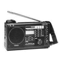
Identifies and labels the main controls and indicators on the radio's front panel.
Details the different wave bands (LW, MW, SW) and their frequency ranges for tuning.
Lists key technical parameters like power supply, voltage requirements, and frequency ranges.
Step-by-step instructions for removing the rear casing for access to internal components.
Procedure for diagnosing analogue-digital failures using the built-in service test program.
Guidance on disassembling and servicing the analog circuitry board.
Instructions for accessing and servicing the µP control unit.
Method for stabilizing and adjusting the 54532 kHz oscillator using coil 5106.
Illustrates the main functional blocks and signal paths within the radio receiver.
Details the wideband pre-amplifier, including antenna input stages and switching.
Explains how the radio automatically switches between telescopic and ferroceptor antennas.
Describes the µP's role in controlling the tuning frequency range for different bands.
Details the circuit design and operation of the AM VCO.
Illustrates the CPU, memory, and control logic with connections.
Provides coordinate mapping for components referenced in Circuit Diagram 1.
Shows the physical layout and interconnection of major components on the main PCB.
Illustrates the wiring for the matrix keyboard and LCD driver assemblies.
Details the central processing unit, memory, and interface circuits.
Lists critical DC voltage measurements required for diagnosis and alignment.
Provides specific procedures for aligning IF stages, oscillators, and filters.
A visual breakdown of the radio's components and their assembly order.
A catalog of replacement parts with their associated part numbers.
Outlines safety requirements for servicing, emphasizing original condition and parts.
Lists common integrated circuits and transistors with their part numbers for easy reference.