5-1 5-1
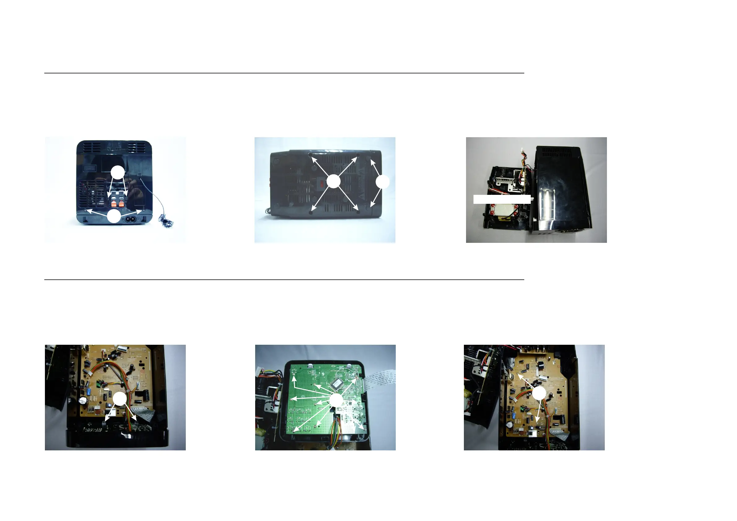
DISASSEMBLY DIAGRAM
BOTTOM CAB.
Dismantling of the Bottom Cabinet
Dismantling of the Front Cabinet and PCB Board.
1)Remove 2 screws E as indicated to loosen the Front Cabinet.
2)Remove 9 screws F as indicated to loosen the Front Board.
3)Remove 2 screw G as indicated to loosen the Main Board.
A
B
E
F
G
C
D
1)Remove 2 screws A as indicated.
2)Remove 2 screws B as indicated to loosen the Speaker Socket Board.
3)Remove 2 foot rubbers first and then remove 2 screws C as indicated.
4)Remove 4 screws D as indicated to loosen the Bottom Cabinet.