EasyManua.ls Logo

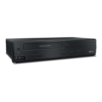
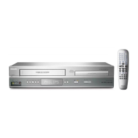
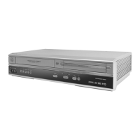
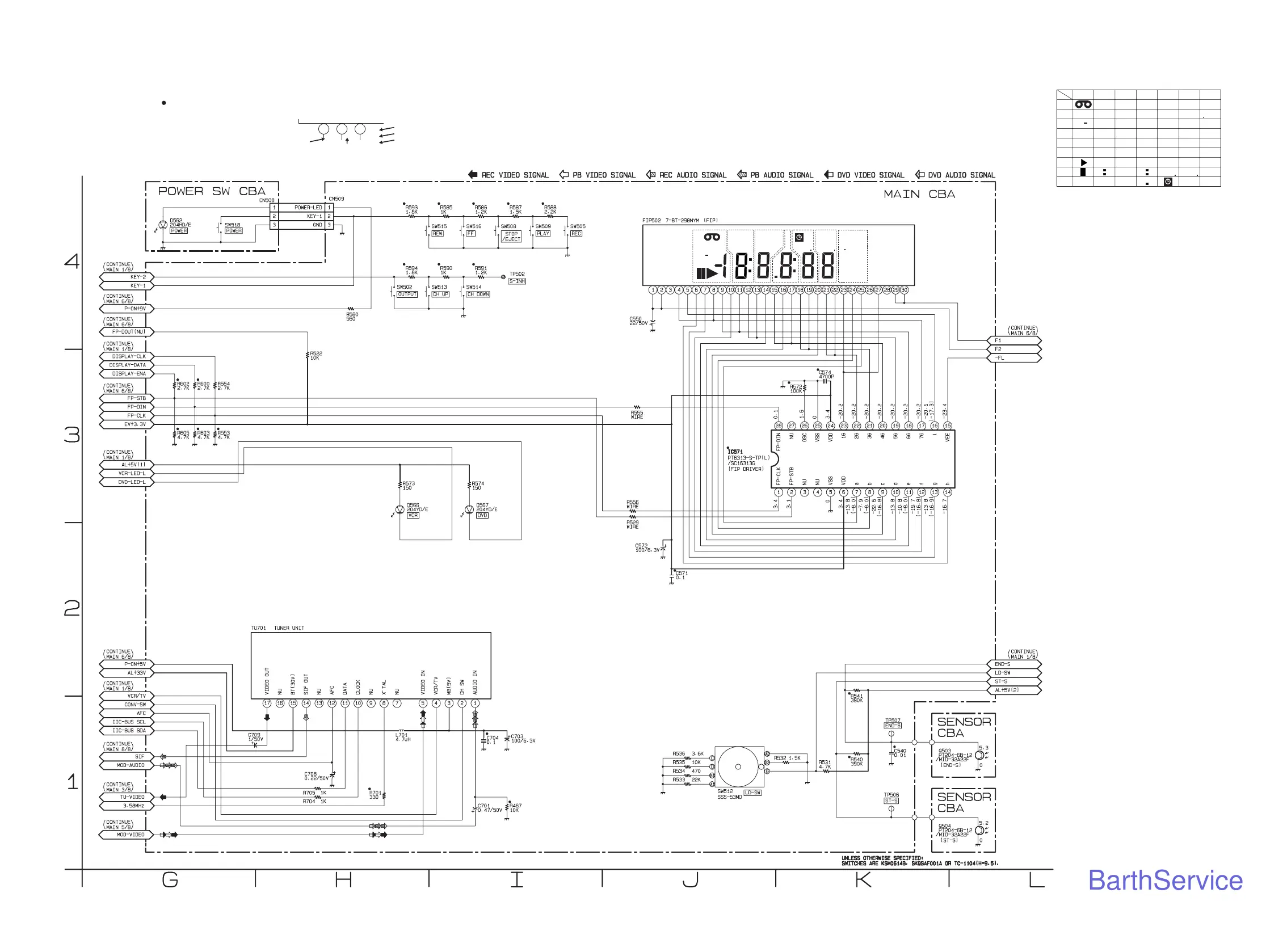
Philips DVP3150V/37 - Main 2;8, Power SW & Sensor Schematic Diagram < VCR Section >

Philips DVP3150V/37
114 pages
Print Icon
To Next Page IconTo Next Page
To Previous Page IconTo Previous Page
Loading...
Main 2/8, Power SW & Sensor Schematic Diagram < VCR Section >
E8A20SCM2
1-13-4
7G 6G 5G 4G 3G 2G 1G
a
b
c
d
e
f
g
c
d
e
ff
g
c
d
e
f
g
c
d
e
f
g
c
d
e
f
g
c
d
e
f
g
h
ii
a
b
a
b
a
b
a
b
a
b
FIP502 MATRIX CHART
REPEAT
TITLE
GROUP
VCR
CHP
REC
SACD
TRK
ALL
B
PSCAN
DVD
P
M
HD
V
CD
A
A
5G 4G 3G 2G 1G
7G
6G
a
d
g
c
b
ef
f
i
i
REPEAT
TITLE
GROUP
VCR
CHP
REC
SACD
TRK
A
ALL
B
PSCAN
DVD
PM
HD
V
CD
A
ā€œ ā€œ = SMD
PLAY mode
REC mode
DVD mode
Voltage indications for PLAY, REC and DVD modes
on the Schematic Diagrams are as shown below:
1 2 3
5.0
(2.5)
<
0
>
~
5.0
The same voltage for
PLAY, REC & DVD modes.
Indicates that the voltage
is not consistent here.
BarthService