2-3
Mechanical and Dismantling Instructions
Dismantling Instruction
Figure
5
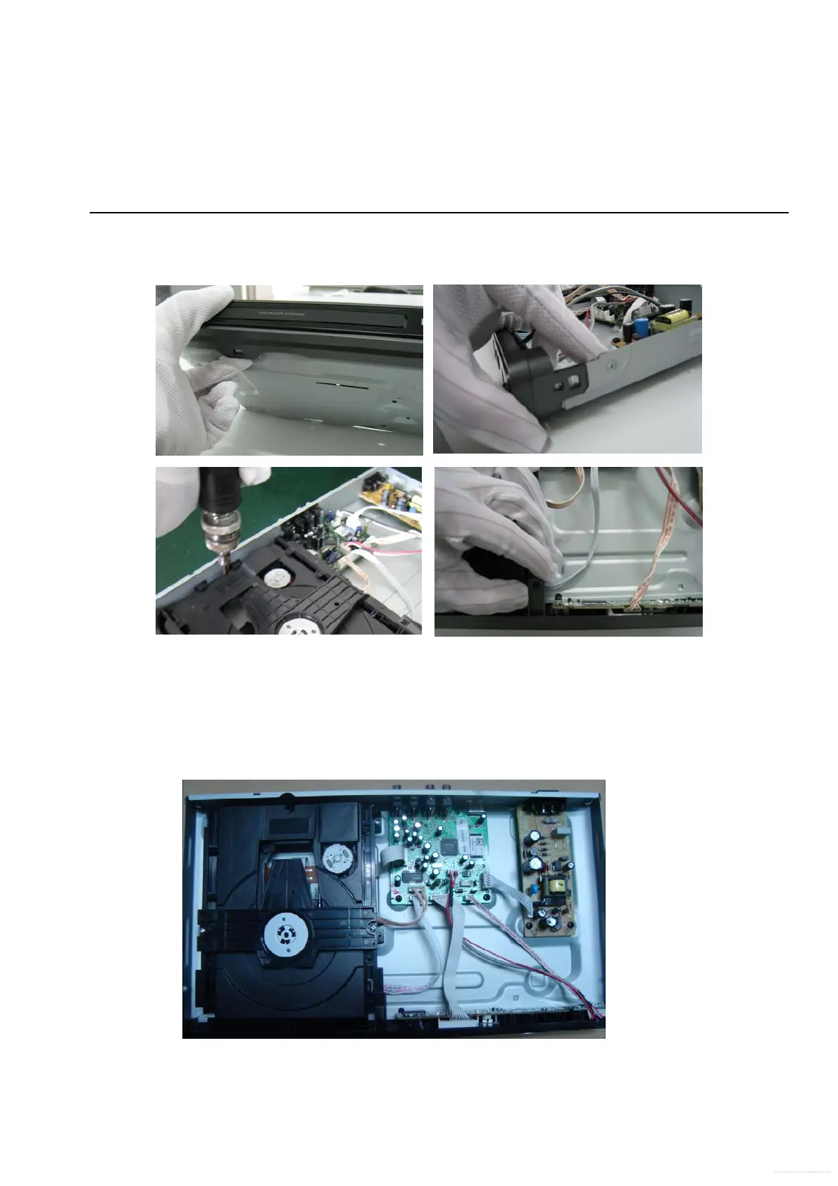
Figure 6
Detailed information please refer to the model set.
St
ep6: Dismantling Main Board, first disconnect the connector (XP1), and then remove 5 screws. (Figure 6)
Step7: Remove the 4 screws on Power Board to dismantle the Power Board. (Figure 6)
Step5: Dismantling Loader, disconnect the 3 connectors (XP2, XP3, XP4) aiming in the below figure, and remove 1 screw that
connects the loader and the bottom cabinet. (Figure 5)
Free Datasheet http://www.datasheet4u.net/
 Loading...