#
HP_GND
#
TO AF9
123
123
A
B
C
A
B
C
1600 C1
1601 B3
1602 A3
2600 A2
2601 A3
2602 A2
2603 A2
5600 B2
5601 B2
5602 A2
9600 A2
HP
1
HP_DET
HP_RIGHT
HP_LEFT
1
2
3
1600
FE-BT-VK-N
9600
RT-01T
1602
2u2
5602
HP
2600
100n
2603
HP
2601
22n22n
5600
2u2
22n
2602
6
2u2
5601
4
1601
TC38
9
8
7
1
2
3
4
5
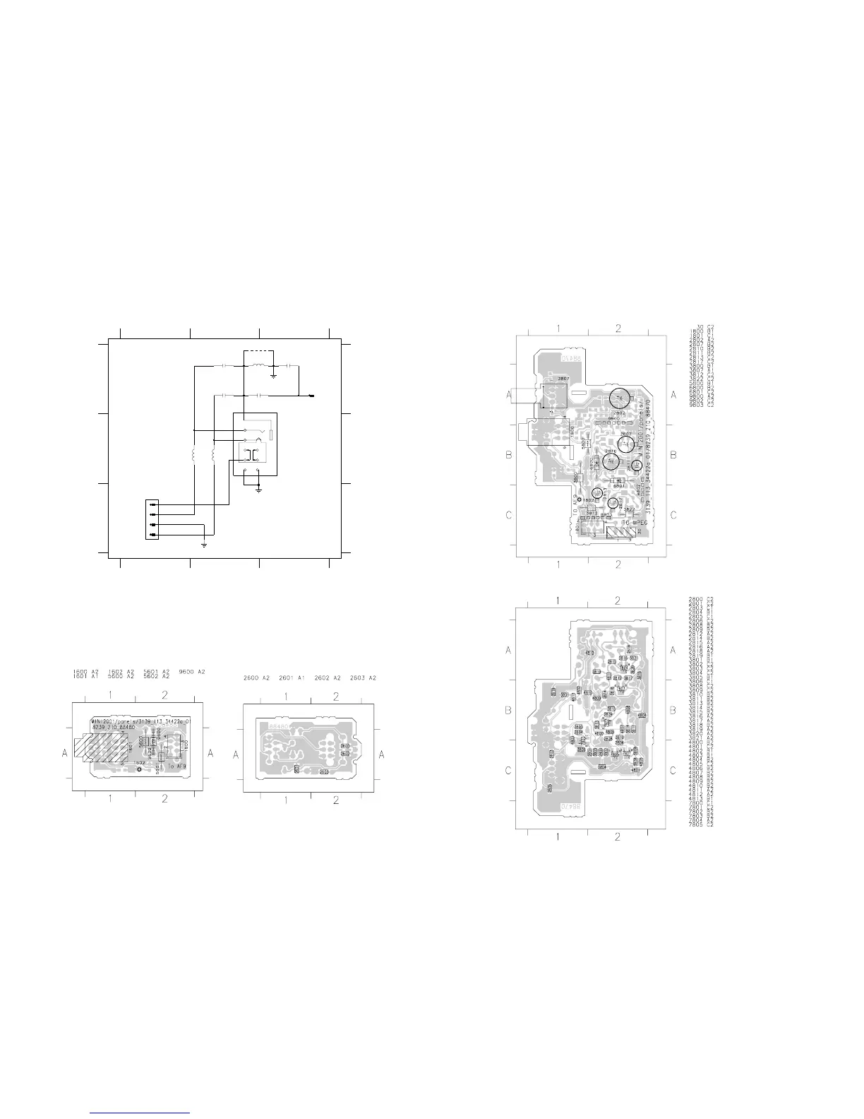
# PROVISION ONLY
3139 118 53880 ... 88480 ...3442 pt 2a dd wk147
HEADPHONE PART - CIRCUIT DIAGRAM
HEADPHONE PART - COMPONENT & CHIP LAYOUTS
KARAOKE PART - COMPONENT & CHIP LAYOUTS
6-6
6-6
3139 113 3442 pt 2a dd wk147
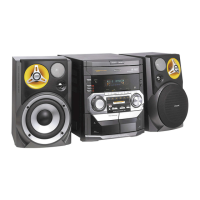
This assembly drawing shows a summary of all possible versions. For
components used in a specific version see schematic diagram and
respective parts list.
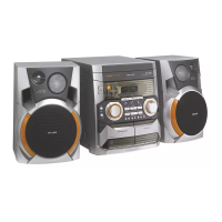
3139 113 3442 pt 2a dd wk147
This assembly drawing shows a summary of all possible versions. For
components used in a specific version see schematic diagram and
respective parts list.
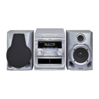
3139 113 3442 pt 2a dd wk147
This assembly drawing shows a summary of all possible versions. For
components used in a specific version see schematic diagram and respective
parts list.
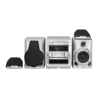
3139 113 3442 pt 2a dd wk147
This assembly drawing shows a summary of all possible versions. For
components used in a specific version see schematic diagram and respective
parts list.