EasyManua.ls Logo

Philips FW-C355 Service Manual

Philips FW-C355
72 pages
To Next Page IconTo Next Page
Page #1 background imageLoading...
Page #1 background image
CLASS 1
LASER PRODUCT
COMPACT
DIGITAL AUDIO
Service Manual
Service
Service
Service
Service
Service
FW-C355/21/22/34
TABLE OF CONTENTS
Page
Location of pc boards & Version variations ................1-2
Technical Specifications .............................................1-3
Measurement setup .................................................... 1-4
Service Aids, Safety Instruction, etc. ..........................1-5
Disassembly Instructions & Service positions .............. 2
Service Test Programs & DEMO mode ......................... 3
Set Block diagram ......................................................... 4
Set Wiring diagram ........................................................ 5
Front Board .................................................................... 6
Mains Board ................................................................... 8
ETF7 Tape Module ........................................................ 9
3CDC-LLC-MCD1 Module ........................................... 10
Combi Board ................................................................ 11
Set Mechanical Exploded view & parts list ................. 12
©
Copyright 2002 Philips Consumer Electronics B.V. Eindhoven, The Netherlands
All rights reserved. No part of this publication may be reproduced, stored in a retrieval system or
transmitted, in any form or by any means, electronic, mechanical, photocopying, or otherwise
without the prior permission of Philips.
Published by KC 0203 Service Audio Printed in The Netherlands Subject to modification
GB
3139 785 30028
Mini System
Version 1.0

Table of Contents

Other manuals for Philips FW-C355

Question and Answer IconNeed help?

Do you have a question about the Philips FW-C355 and is the answer not in the manual?

Philips FW-C355 Specifications

General IconGeneral
BrandPhilips
ModelFW-C355
CategoryStereo System
LanguageEnglish

Summary

Location of PC Boards and Version Variations

Location of PC Boards

Identifies the physical location of circuit boards within the unit.

Specifications

TUNER

FM and MW tuning ranges, sensitivity, selectivity, and distortion.

COMPACT DISC

CD measurement setup and specifications like frequency response and S/N.

AMPLIFIER

Output power, frequency response, and headphone output specs.

Measurement Setup

ESD Protection Measures

Dismantling Instructions

Dismantling the 3CDC Module

Step-by-step guide to disassemble the 3-disc CD changer module.

Dismantling of the Front Panel Assembly

Steps to disassemble the front panel assembly.

Dismantling of Bottom & Rear Panel Assembly

Guide to disassembling the bottom and rear panel.

Service Test Program

TUNER TEST

Procedure for testing the tuner section.

SERVICE PLAY MODE

How to activate and use the service play mode for CD.

Error Codes and Descriptions

Table of error codes and their descriptions for troubleshooting.

Test Modes and Actions

Various test modes and their associated actions.

Set Block Diagram

MAIN SIGNAL PATH

Diagram showing the main signal flow through the unit.

Set Wiring Diagram

Connector Assignments

Details interface connections between modules.

Front Board

Circuit Diagram - Microprocessor Part

Electrical Parts List - Front Board

Electrical Parts List - Front Board (Continued)

Mains Board

Circuit Diagram

Schematic diagram of the mains board circuitry.

Mains Circuit

Electrical Parts List - Mains Board

ETF7 Tape Module (Non-Dolby Version)

Tapedeck Wiring (Double Deck)

Wiring diagram for the double deck tape mechanism.

Block Diagram (Tape Module)

Connectors Assignments

DECK A & B CONTROL INTERFACE

Control interface for decks A & B (Dolby and Non-Dolby).

Tape Mechanism Electronics

TAPE ADJUSTMENT & CHECK TABLE

Table for tape mechanism adjustments and checks.

ADJUST MOTOR SPEED

Procedure for adjusting motor speed.

ADJUST AZIMUTH

Procedure for adjusting azimuth.

ADJUST BIAS CURRENT

Procedure for adjusting bias current.

3CDC-LLC-MCD1 (3 Disc Carousel Changer)

System Diagrams

Block diagram, circuit diagrams, and layouts for the CD changer.

Exploded View and Parts List

Visual breakdown and list of parts for the CD changer mechanism.

Service Hints (CD Mechanism)

Service Hints (Tray)

BLOCK DIAGRAM 3CDC-LLC-MCD1

3CDC-LLC Mainboard Part 1 Circuit Diagram

HF-Amplifier and Signal Processor Circuits

Circuit diagrams for HF amplifier and signal processor.

3CDC-LLC Mainboard Part 2 Circuit Diagram

Digital Circuitry and Changer Control

Digital circuit diagrams and changer control logic.

Exploded View (3CDC-LC Module)

Electrical Parts List - 3CDC-LLC-MCD1 Module

Electrical Parts List - 3CDC-LLC-MCD1 Module (Continued)

Combi Board

Key Circuit Diagrams

Schematics for Power Supply, Source Selection, Amplifiers, and Transformers.

Tuner Section Details

Layouts, adjustments, and circuits for Non-Cenelec and Cenelec Tuners.

Electrical Parts List

List of electronic parts for the Combi board.

Power Supply Circuit (Combi Board)

Source Selection Circuit (Combi Board)

Pre- & Power Amplifier Circuit (Combi Board)

Non-Cenelec Tuner Portion - Component & Chip Layouts

Cenelec Tuner Portion - Component & Chip Layouts

VARICAP ALIGNMENT

Tuning adjustment table for varicap alignment.
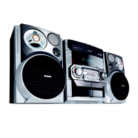
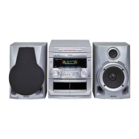
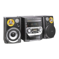
Cenelec Tuner Circuit

Electrical Parts List - Combi Board (excluding Tuner portion)

Electrical Parts List - Combi Board (excluding Tuner portion) (Continued)

Electrical Parts List - Combi Board (Non-Cenelec Tuner portion only)

Electrical Parts List - Combi Board (Cenelec Tuner portion only)

Exploded View - Main Unit

Mechanical & Accessories Parts List - Main Unit

Related product manuals