Do you have a question about the Philips FWD570/21M and is the answer not in the manual?
Table detailing features and variations across different model versions.
Detailed specs for Amplifier, Tuner, Tape, DVD, Main Unit, and Speakers.
Diagrams for setting up measurement equipment for tuner and recorder functions.
Lists essential tools, ESD protection gear, and diagnostic discs for service.
Guidelines, precautions, and visual examples for handling chip components safely.
Safety guidelines for ESD and post-service leakage current measurement.
Guide for setting the TV video system (NTSC, PAL, AUTO).
Instructions for speaker setup, language selection, and connections.
Details on connecting TV via CVBS, Component, and S-Video inputs.
Guides for connecting antennas, power cord, VCR, audio devices, and game consoles.
Description of system unit controls and remote control operations.
Troubleshooting guide for common issues like no power, poor picture, and no sound.
Guides for system reset, region code, tuner area, password, and software upgrades.
Flowchart to diagnose and troubleshoot malfunctions of the main unit.
Step-by-step guides for disassembling the cassette cover and 3CDC module.
Instructions for detaching the main board, rear panel, and power board assemblies.
Illustrates different positions for efficient and safe servicing of the unit.
Block diagrams illustrating the internal circuitry of main ICs like ES6698 and TDA8920.
Diagram showing the complete wiring layout and connections between system components.
Pin assignments, IC diagrams, and circuit details for the board.
Details the internal structure and pin functions of the VFD controller IC.
Detailed circuit diagram and component mapping for the key board.
Top view layout showing component placement and reference designators.
Top view layout detailing component placement and reference designators.
Bottom view layout showing component placement and reference designators.
List of electrical components specific to the key board.
List of components for VFD, control, game, mic, and phone boards.
Adjustment procedures and values for tuner alignment stages.
Top view circuit diagram and component placement for the tuner board.
Bottom view layout showing component placement and reference designators.
Internal block diagrams of key ICs used on the main board.
Detailed circuit diagram illustrating the main board's complete circuitry.
Cross-reference of components to their locations on the main board (main part).
Cross-reference of components to their locations on the main board (servo part).
Detailed circuit diagram for the servo section of the main board.
Detailed circuit diagram for the tape section of the main board.
Schematic mapping and top view PCB layout for the tape part.
Top view layout showing component placement and reference designators for the main board.
Bottom view layout showing component placement and reference designators for the main board.
Cross-reference of components to their locations on the main board (bottom view).
Complete list of electrical components for the main board.
Internal block diagrams of KA7500C and KA5M02659RN ICs.
Detailed circuit diagram for the power board.
Diagram showing component placement and reference designators for the power board.
Comprehensive list of electrical components for the power board.
Exploded view of mechanical assembly and a list of screws used.
List of mechanical and accessory parts with part numbers.
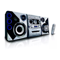
| Type | Stereo System |
|---|---|
| Brand | Philips |
| Model | FWD570/21M |
| Audio Formats Supported | MP3 |
| RDS | Yes |
| Bluetooth | No |
| Remote Control | Yes |
| Disc Playback | CD |
| Tuner | FM |
| Connectivity | AUX in |
| Speakers | 2-way bass reflex |