Circuit Descriptions, Abbreviation List, and IC Data Sheets
EN 56 LC4.1E AB9.
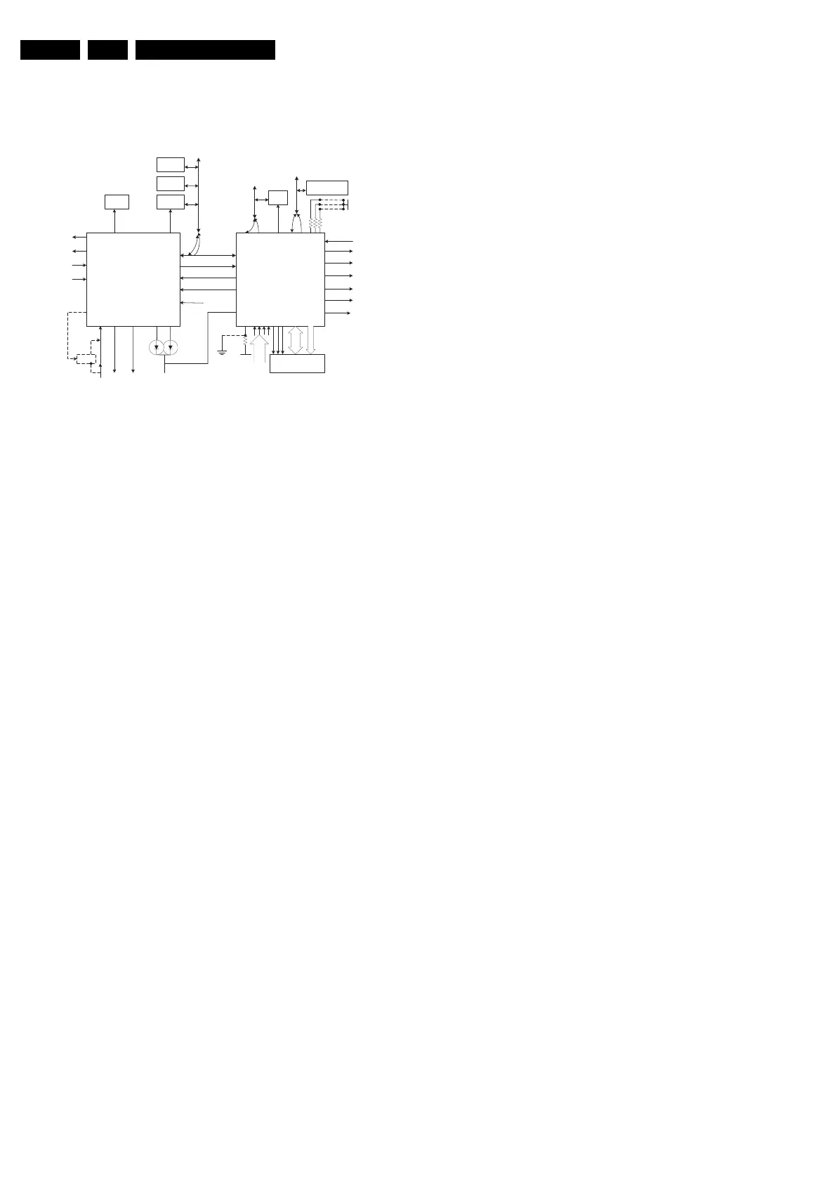
9.8.2 Block Diagram
The block diagram of the Micro Controller application is shown
below.
Figure 9-4 Micro Controller block diagram
9.8.3 Basic Specification
The Micro Controller operates at the following supply voltages:
• +3.3 V_dc at pins 4, 88, 94, and 109.
• +1.8 V_dc at pins 93, 96, and 117.
• I2C pull up supply: +3.3V_dc.
9.8.4 Pin Configuration and Functionality
The ports of the Micro Controller can be configured as follows:
• A normal input port.
• An input ADC port.
• An output Open Drain port.
• An output Push-Pull port.
• An output PWM port.
• Input/Output Port
9.9 LCD Display
9.9.1 Specifications
Panel model : LC150X02 (15”)
: LC201V02 (20”)
: QD23WL04 (23”)
Resolution (HxV) : 1024x768 pixels (15”)
: 640x480 pixels (20”)
: 1366x768 pixels (23”)
Luminance : 450 nit
Supplier : LG.Philips LCD (15”,
20”)
: Quanta Displays Inc.
(15”)
: AU Optronics (20”)
: ???? (23”)
9.10 Abbreviation List
0/6/12 SCART switch control signal on A/V
board. 0 = loop through (AUX to TV), 6
= play 16:9 format, 12 = play 4:3
format
1080i 1080 visible lines, interlaced
1080p 1080 visible lines, progressive scan
2CS 2 Carrier Stereo
480i 480 visible lines, interlaced
480p 480 visible lines, progressive scan
ACI Automatic Channel Installation:
algorithm that installs TV channels
directly from a cable network by
means of a predefined TXT page
ADC Analogue to Digital Converter
AFC Automatic Frequency Control: control
signal used to tune to the correct
frequency
AGC Automatic Gain Control: algorithm that
controls the video input of the feature
box
AM Amplitude Modulation
AP Asia Pacific
AR Aspect Ratio: 4 by 3 or 16 by 9
ASD Automatic Standard Detection
AV Audio Video
B-SC1-IN Blue SCART1 in
B-SC2-IN Blue SCART2 in
B-TXT Blue teletext
B/G Monochrome TV system. Sound
carrier distance is 5.5 MHz
BOCMA Bimos one Chip Mid-end Architecture:
video and chroma decoder
C-FRONT Chrominance front input
CBA Circuit Board Assembly (or PWB)
CL Constant Level: audio output to
connect with an external amplifier
CLUT Colour Look Up Table
ComPair Computer aided rePair
CSM Customer Service Mode
CVBS Composite Video Blanking and
Synchronisation
CVBS-EXT CVBS signal from external source
(VCR, VCD, etc.)
CVBS-INT CVBS signal from Tuner
CVBS-MON CVBS monitor signal
CVBS-TER-OUT CVBS terrestrial out
DAC Digital to Analogue Converter
DBE Dynamic Bass Enhancement: extra
low frequency amplification
DFU Directions For Use: owner's manual
DNR Dynamic Noise Reduction
DRAM Dynamic RAM
DSP Digital Signal Processing
DST Dealer Service Tool: special
(European) remote control designed
for service technicians
DTS Digital Theatre System (a sound
system, similar to Dolby Digital)
DVD Digital Versatile Disc
EEPROM Electrically Erasable and
Programmable Read Only Memory
EPG Electronic Program Guide: system
used by broadcasters to transmit TV
guide information (= NexTView)
EPLD Electrically Programmable Logic
Device
EU EUrope
EXT EXTernal (source), entering the set by
SCART or by cinches (jacks)
FBL Fast Blanking: DC signal
accompanying RGB signals
FBL-SC1-IN Fast blanking signal for SCART1 in
HERCULES SCALER
Tuner
ComPair
NVM
Sound
Amp
MUX
NVM
GPROBE for Debug
or ComPair(Scaler)
SDA
SCL
TV_IRQ
TV_SC_COM
+3V3STBY
1407
1406
1405
PC_DET
SD_PCHD_SEL
PC_HD_SEL
POWER_DOWN
LAMP_ON_OFF
PANEL_PWR_CTL
HD_FILTER
BACK_LIGHT_ADJ1
Flash ROM
83
GPIO2
NVM_WP
IIC BUS 2
93
NVRAM
_SDA
92
NVRAM
_SCL
72
71
187193194
85
(GPIO4)
88
(GPIO5)
89
(GPIO6)
68
(PBIAS)
67
(PPWR)
99
(PWM1)
98
(GPIO11/
PWM0)
78 DDC_SDA_VGA
77 DDC_SCL_VGA
82 GPIO1
81 GPIO0
+3V3STBY
111
GPIO23
90 GPIO7
ROM_ADD0-17
ROM_DATA0-7
5 6 7
103 106 107 108
HIGH or
LOW
level input
IIC BUS1
NVM_WP
Sound_Enable
HREC
RST
Sel IF/
SDM
Status1
Light
Sense
TV_IR
RC
P50_LINE_ITV_IR_SW
EXT_MUTE
Standby
POWER
DOWN
127
P1.4
114
P2.3
116
ADC1
115
ADC0
123
P2.5
97
INT0
102
P0.4
122
P2.4
126
INT2
128
P1.5
SDA 109
SCL 108
INT1 98
P1.1 99
Keyboard
ADC3 120
111
P2.0
104
P0.2
E_14490_062.eps
160904