Mechanical Instructions
EN 14 LC7.1E LA4.
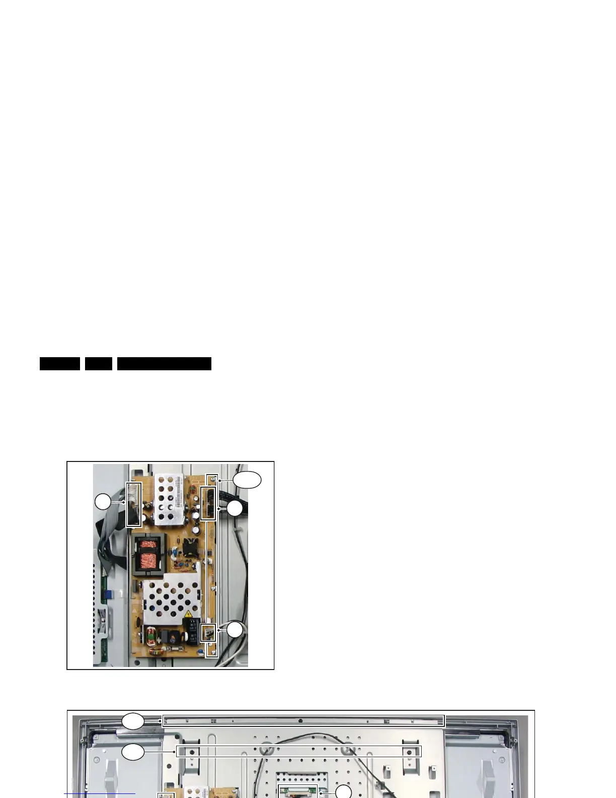
4.3.8 Main Supply Panel
1. Remove the rear cover, as described earlier.
2. Refer to fig. “Main supply panel“ below.
3. Unplug cables [a].
4. Remove the fixation screws [b].
5. Take the board out (it hinges at the left side).
Figure 4-14 Main supply panel
4.3.9 LCD Panel
1. Remove the rear cover, as described earlier.
2. Refer to fig. “LCD panel“ below.
3. Unplug the connectors on the Main Supply Panel [a] and
the LED & IR board [c].
4. Unplug the outer connectors [d] from the mid-range
loudspeakers.
5. Do NOT forget to unplug the LVDS connector [e] from the
SSB. Important: Be careful, as this is a very fragile
connector!
6. Remove T10 parker screw [b] that holds the Side I/O
module bracket.
7. Remove T10 parker screws [f] of the central sub-frame.
8. Remove LCD panel fixation screws [g] and lift the complete
central sub-frame from the set (incl. the PSU, SSB, and
Side I/O boards and wiring).
9. Lift the LCD panel [7] from the front cabinet.
Figure 4-15 LCD panel [1/2]
G_16860_065.ep