Circuit Descriptions, Abbreviation List, and IC Data Sheets
EN 75LC7.1E LA 9.
9.2 LCD Power Supply
The Power Supply Unit (PSU) in this chassis is a buy-in and is
a black-box for Service. When defective, a new panel must be
ordered and the defective panel must be sent for repair, unless
the main fuse of the unit is broken. Always replace the fuse with
one with the correct specifications! This part is available in the
regular market.
Three different PSU can be used in this chassis:
• 26 and 32 inch sets use a “Delta” PSU
• 37 and 42 inch sets use a “PPS” (Philips Power Solutions)
PSU
• 47 inch sets use a “Delta” PSU.
Figure “Overview of PSU connectivity” shows the connectivity
of the Power Supply Unit with the other panels in the set.
Figure 9-3 Overview of PSU connectivity
All Power Supply Units deliver the following voltages to the
chassis:
• +24 V to the inverters
• +12 V to SSB
• +12 V and -12 V to Audio Supply
• 12 V to Bolt-on Supply (where applicable)
• +5.2 V Standby voltage.
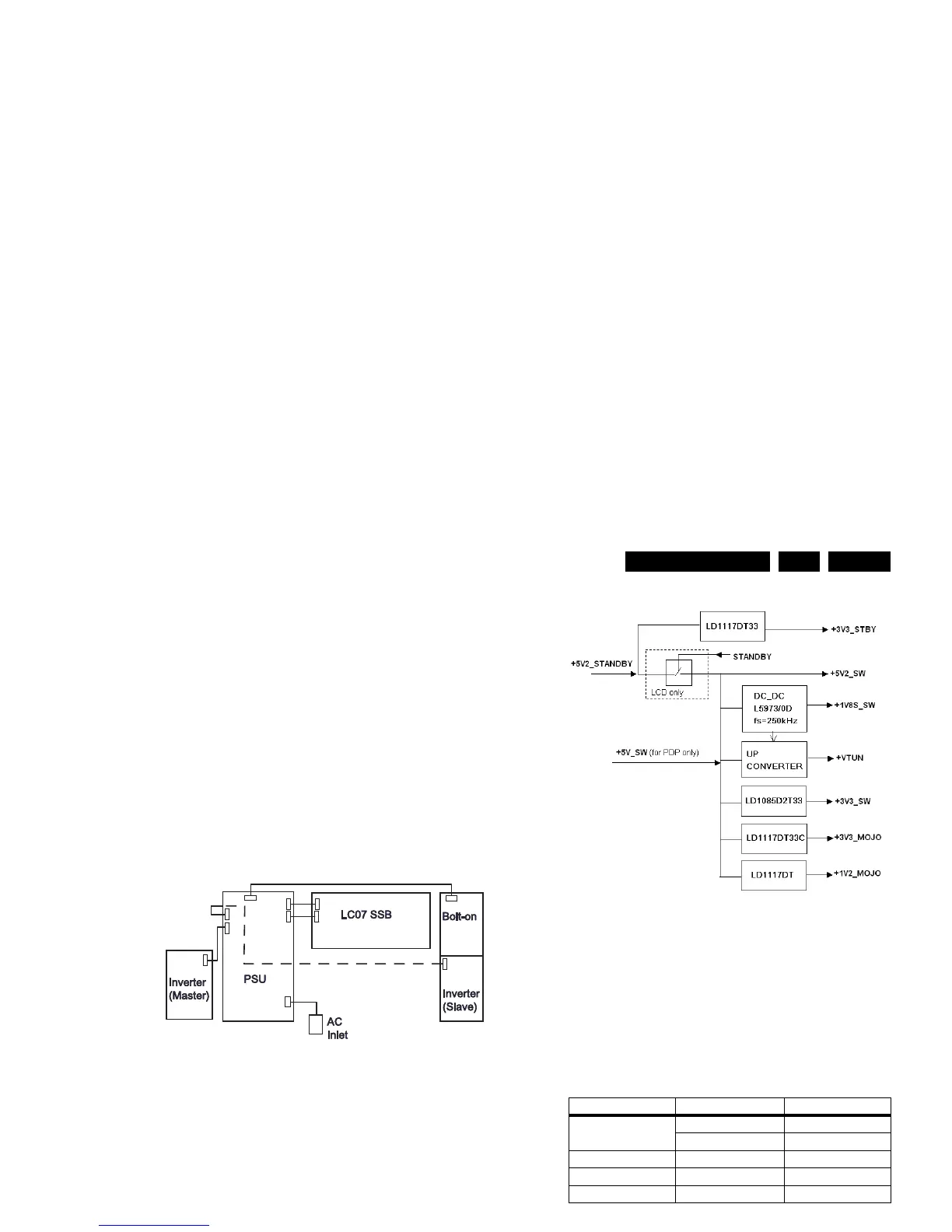
9.3 DC/DC converters
A switch generates the +5.2 V (+5V_SW) from the +5.2 V
(+5V_STANDBY) supply voltage. For LCD sets, this switch is
mounted on-board the SSB. For PDP sets, this switch is
mounted on the Power Supply Panel. This results in the
+5V_STANDBY (and +5V_SW for PDP sets) voltage(s),
coming from the Power Supply Unit, is (are) used as input for
the on-board DC/DC converters.
They deliver the following voltages to the board:
• +3.3 V (+3V3_STBY)
• +5.2 V (+5V_SW) (only for LCD sets)
• +1.8 V (+1V8S_SW)
• +34 V (+VTUN)
• +3.3 V (+3V3_SW)
• +3.3 V (+3V3_MOJO)
• +1.2 V (+1V2_MOJO)
An overview can be found in figure “DC-DC converter block
diagram”.
Figure 9-4 DC-DC converter block diagram
9.4 Front-End
This chassis uses different tuners depending on the region and
execution. An overview of the different executions can be found
in table “Tuner diversity”.
Table 9-1 Tuner diversity
For a general outline of tuner applications in this chassis see
figure “Tuner IF diagram”.
Figure 9-5 Tuner IF diagram
In the LC7.1x chassis (analogue sets), the signal coming from
the tuner is fed to the IF demodulator (through the SAW filters)
and then passed to the Trident Video Processor.
In the LC7.2x chassis (digital sets), the TD1316AF hybrid tuner
is used which is capable of receiving both analogue and digital
(DVB-T) signals. While receiving analogue signals, the signal
coming from the tuner is fed to the IF demodulator (through the
SAW filters) and then passed to the Trident Video Processor.
While receiving digital signals, the signal coming from the tuner
is first fed to the channel decoder, then to the MPEG decoder
and then to the Trident Video Processor.
G_16860_051.eps
310107
Region Tuner Type
Europe TD1316AF hybrid
UV1318S analogue
AP UV1316E analogue
China TEDE9 analogue
Latam UV1338 analogue
G_16860_063.eps
310107
Tuner
Video
SAW filter
Audio
SAW filter
Switch IC
IF Demodulator
CVBS
2
nd
SIF
Digital IF
36.16MHz
4MHz
RFAGC
RF AGC_analogue
I
2
C
IF AGC
Supply
+5V/+33V
RF AGC_digital
I
2
C_analogue
I
2
C_digital
G_16860_054.eps
020207