Circuit Descriptions, Abbreviation List, and IC Data Sheets
EN 77LC7.1E LA 9.
9.5.1 Region-dependent applications
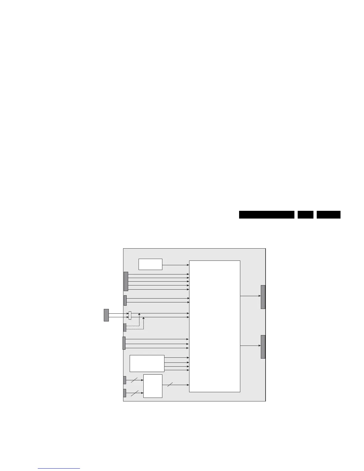
Figure 9-6 Block diagram video processing - EU version
“Block diagram video processing - EU version” shows the input
and output signals to and from the Trident Video Processor in
EU applications.
During analogue reception, a CVBS signal coming from the
analogue front-end is fed to the video processor via pin
CVBS1. During digital reception, the video signal coming from
the MPEG decoder (MOJO) is fed to the video processor via
pins FS1, PC_B, PC_G and PC_R.
The video processor also interfaces the SCART1 & 2 input,
side AV, EXT4 (HD where applicable) and HDMI1 & 2 input.
Through the SCART1 & 2 connectors, a monitor output is
foreseen.
Figure 9-7 Block diagram video processing - AP version
IBO _ R _IN
Trident
Video Processor
SVP CX32
( D V B-T
demodulator
Digital Front End
and decoder)
CVBS
SCART1
SC1_R_IN
SC1_CVBS_IN
SC1_FBL_IN
HD_Y_IN
SCART2
SIDE AV
FRONT_Y_CVBS_IN_T
SC2_Y_CVBS_IN
EXT4
HDMI
Decoder
HDMI1
HDMI2
HDMI_Y(0:7)
HDMI_Cb(0:7)
HDMI_Cr(0:7)
SCART2 Monitor out
On board EXT3
CVBS
SCART1 Monitor out
PR_R2
PB_B2
Y_G2
SC1_G_IN
SC1_B_IN
PB_B3
FB1
IBO _ G _IN
IBO _ B _IN
IBO _ C VB S _ IN
PC_R
PC_G
PC_B
FS1
HD_PB_IN
HD_PR_IN
Y_G1
PB_B1
PR_R1
SC2_C_IN
FRONT_C_IN_T
Y_G3
C
PR_R3
FS2
CVBS_OUT1
CVBS_OUT2
Analogue
Front End
CVBS_RF
CVBS1
G_16860_060.eps
310107
IBO _R_IN
MUX
CVBS
PC VGA
SC1_R_IN
PC_VGA_H
PC_VGA_V
HD_Y_IN
AV1
SIDE AV
FRONT_Y_CVBS_IN_T
SC2_Y_CVBS_IN
CVI2
HDMI1
HDMI2
HDMI_Y(0:7)
HDMI_Cb(0:7)
HDMI_Cr(0:7)
CINCH Monitor out
PR_R2
PB_B2
Y_G2
SC1_G_IN
SC1_B_IN
AIN_HS
AIN_VS
IBO _G_IN
IBO _B _IN
IBO_CV BS_IN
PC_R
PC_G
PC_B
FS1
HD_PB_IN
HD_PR_IN
Y_G1
PB_B1
PR_R1
SC2_C_IN
FRONT_C_IN_T
Y_G3
C
PR_R3
FS2
CVBS_OUT2
Analogue
Front End
CVBS_RF
CVBS1
DMMI YPbPr IN
CVI YPbPr
CVI1
DMMI connector
CVI_DTV_SEL
Trident
Video Processor
SVP CX32
HDMI
Decoder
G_16860_061.eps
310107