Mechanical Instructions
EN 12 LC7.1HE LA4.
4.2 Service Positions
For easy servicing of this set, there are a few possibilities
created:
• The buffers from the packaging.
• Foam bars (created for Service).
• Aluminium service stands (created for Service).
Note: the aluminium service stands can only be used when the
set is equipped with so-called “mushrooms”. Otherwise use the
original stand that comes with the set.
4.2.1 Foam Bars
Figure 4-4 Foam bars
The foam bars (order code 3122 785 90580 for two pieces) can
be used for all types and sizes of Flat TVs. See figure “Foam
bars” for details.
Sets with a display of 42" and larger, require four foam bars [1].
Ensure that the foam bars are always supporting the cabinet
and never only the display.
Caution: Failure to follow these guidelines can seriously
damage the display!
By laying the TV face down on the (ESD protective) foam bars,
a stable situation is created to perform measurements and
alignments. By placing a mirror under the TV, you can monitor
the screen.
4.2.2 Aluminium Stands
Figure 4-5 Aluminium stands
The MkII aluminium stands with order code 3122 785 90690,
can also be used to do measurements, alignments, and
duration tests. The stands can be (dis)mounted quick and easy
by means of sliding them in/out the “mushrooms”. The stands
are backwards compatible with the earlier models.
Important: For (older) FTV sets without these “mushrooms”, it
is obligatory to use the provided screws, otherwise it is possible
to damage the monitor inside!
4.3 Assy/Panel Removal
4.3.1 Rear Cover
Warning: Disconnect the mains power cord before you remove
the rear cover.
1. Place the TV set upside down on a table top, using the
foam bars (see part “Service Position”).
2. Remove rear cover screws and the stand (if mounted).
3. Remove rear cover.
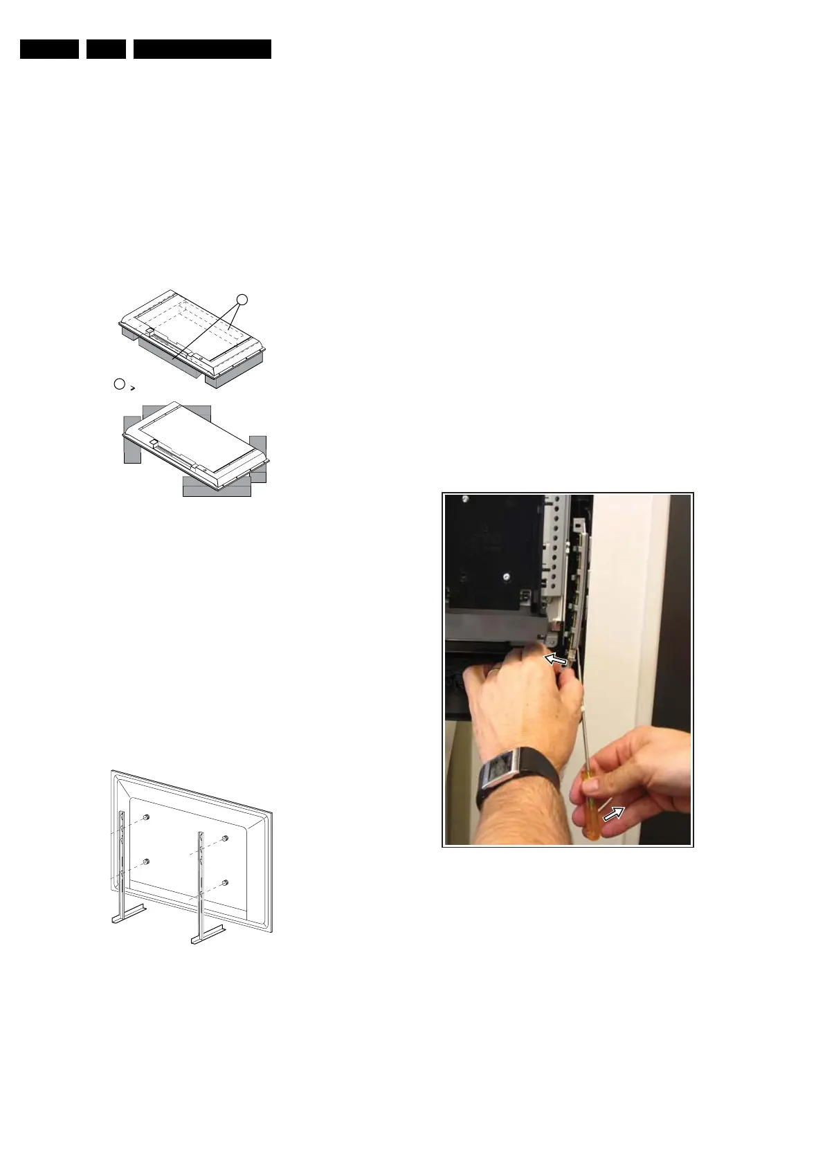
4.3.2 Keyboard Control Panel
1. Refer to next figure (taken from the 32" model, but the
method is comparable for the other screen sizes).
2. Remove the all screws.
3. Unplug connector.
4. Remove the unit.
Note: as the unit is “secured” by bosses located on the
front cabinet, it can be difficult to remove the unit.
Therefore, it is advised to use a long thin screwdriver,
insert it vertically between the control knobs and the front
cabinet, and use it as a lever (see arrows) while pulling the
unit from the cabinet. You will here some “clicks” during
removal.
5. Release clips and remove the board.
When defective, replace the whole unit.
Figure 4-6 Keyboard control panel
4.3.3 IR/LED Panel
1. Remove the rear cover, as described earlier.
2. Refer to fig. “IR/LED panel” below.
3. Unplug connector(s) [1].
4. Release clip [2] and remove the board.
When defective, replace the whole unit.
E_06532_018.eps
171106
1
Required for sets
42"
1
E_06532_039.eps
290507
H_16990_051.eps
270707
 Loading...


