8
2 INSTALLATION
2.1 Ventilation
In order to prevent overheating, ensure that the ventilation
openings on the monitor are not covered.
2.2 Power
Model Rated Voltage Power at Sync
No. Voltage Range Rated Voltage Format
LTC 2914/91 120/230 VAC 90 to 264 75 W PAL/
50/60 Hz NTSC
LTC 2917/91 120/230 VAC 90 to 264 80 W PAL/
50/60 Hz NTSC
LTC 2919/90 120/230 VAC 90 to 264 90 W PAL/
50/60 Hz NTSC
The LTC 2914/91, LTC 2917/91, and LTC 2919/90 monitors
are delivered with a 3-pole US style power cord and a 3-pole Euro
style power cord. The US style power cord is used where 120
VAC, 60 Hz power is available, and the Euro style power cord is
used where 230 VAC, 50 Hz power is available. The monitor end
of the power cord plugs into mains input socket (Fig 1, Item 13)
on the rear panel. The monitor automatically adjusts to either
power input voltage. A power on/off switch is located on the front
of the unit (Fig 1, Item 7).
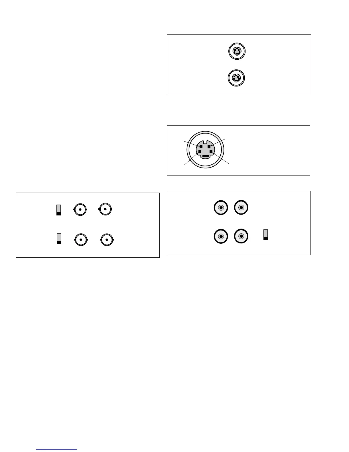
2.3 Connecting Composite Video Signal to the
Monitor
The four (4) BNC connectors (Fig 1, Item 9) located on the
rear of the monitor are for composite video inputs and outputs.
NOTE: All video inputs are passive loop-through. In a single
connection mode, the impedance must be set to 75 Ohm by
sliding the impedance switch to the
75 Ω position. In the
multiple connector mode (Fig 3a & 3b), the impedance switch
is set to the HiZ position. This allows the video signal to be
passed on to another monitor or device.
CAUTION: The last monitor or device in the chain which is
receiving the video signal must be terminated, i.e., the
impedance switch set to the 75 Ω position (Fig 3b).
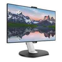
2.4 Connecting Y/C (S-video) Signal to the Monitor
There are two (2) mini-DIN type connectors (Fig 1, Item 12):
one for Y/C input (IN) and one for a loop-through Y/C output
(OUT) to another device.
NOTE: The video input is passive loop-through.
2.5 Connecting Audio to the Monitor
There are two sets of monaural audio connectors (Fig 1, Item
10): one for audio input and the other for a loop-through
output to another device.
NOTE: AUDIO A is associated with VIDEO A; and AUDIO
B with both VIDEO B & VIDEO Y/C.
3 OPERATION
3.1 Front Panel Controls (Fig 1)
OSD (#1): Selects on-screen display (OSD); saves settings.
(#2 up): Multifunction; First push – selects brightness
function for adjustment; In brightness adjust mode – increases
brightness level; Within OSD menu – moves the cursor
upward.
▲
1. GND
2. GND
3. Y-signal IN or OUT
4. C-signal IN or OUT