11-211-2
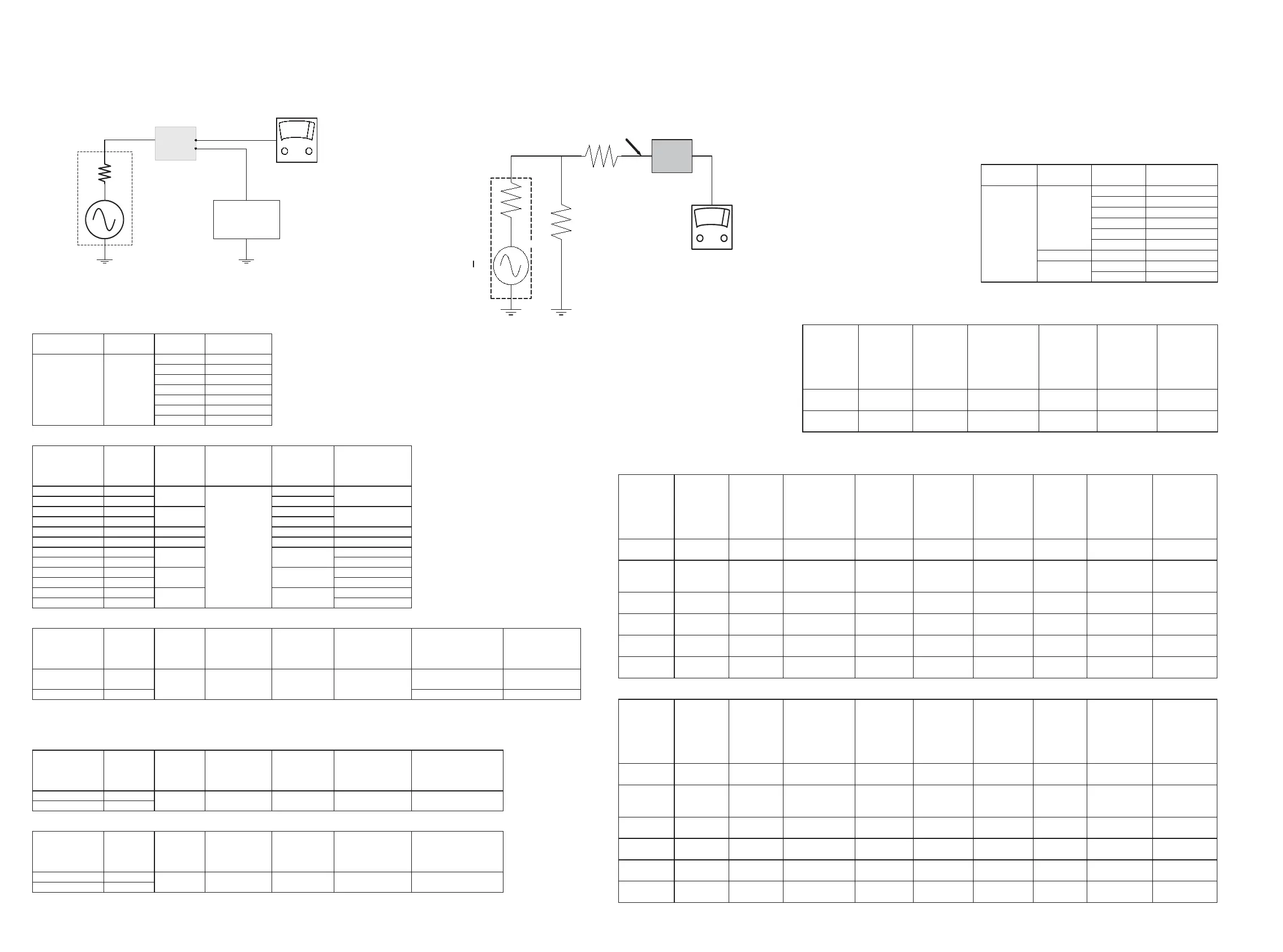
DUT
OUTPUT MEASURING
ANALYSER
wireless transmitter
test circuit
e.g. FAM
from R&S
L + R
LF Generator
e.g. PM5110
AC-mV meter
e.g. PM2534
CL36532008_019.eps
150403
F114
F150
Wireless Transmitter functional check and adjustment table Audio AD905W (LX3750W) versions
Powersupply check
Measurement
ground
testpoint Scope / Voltmeter
F119 +12V ± 0.5V
F124 + 8.35V ± 0.25V
F126 + 5V ± 0.25V
F145 + 2.52V ± 0.2V
F144 + 2.52V ± 0.2V
F147 + 4.2V ± 0.3V
F149 + 4.2V ± 0.3V
picture DUT:
LF input signal
L = 400Hz;
R = 400Hz,
via
input level testpoint
Input and
Measurement
ground
AC Voltmeter Frequency counter
F117 410 mV L
F118 410mV R
F117 410 mV L
F118 410mV R
F117 410 mV L F145 210 mV ± 20 mV
F118 410mV R F144 210 mV ± 20 mV
F117 410 mV L
F118 410mV R
F117 410 mV L
F118 410mV R
F117 2100 mV L
F118 2100 mV R
Check RF output signal
LF input signal
L = 400Hz;
R = 400Hz,
via
input level Input ground channel
Measurement
RF ground
Output signal Frequency counter Version
F117 0 mV L 864.5 ± 0.025 MHz
for EUR and UK
version
F118 0 mV R 915.3 ± 0.025 MHz
for USA version
Alignment of the modulation level *
Method 1
LF input signal
L = 400Hz;
R = 400Hz,
via
input level input ground
Connect RF
Modulation
Analyzer
to testpoint
Measurement
ground
Align
RF Modulation
Analyser deviation
F117 410 mV L
F118 410 mV R
Method 2
LF input signal
L = 400Hz;
R = 400Hz,
via
input level input ground
Connect AC mV
meter
to testpoint
Measurement
ground
Align AC mV meter
F117 410 mV L
F118 410 mV R
* or Method 1 or Method 2 to be applied
4
DC Check
F116 F115 F114
F116
F116
205 mV ± 20 mVF149
F149 380 mV ± 40 mV
F147 200 mV ± 20 mV
23.4375 kHz ± 10 Hz
46.875 kHz ± 20 HzF131
F130
50 kHz ± 3 Hz
80mV rms (= 230mV pp)
3179F115F116 F114
F116 F150 F116
3179
wireless receiver test circuit
68 E
50 E
68 E
To RX input
RF Generator
DUT
LF Voltmeter
e.g. PM2534
CL36532008_020.eps
170403
Powersupply
check
Measurement
ground testpoint Scope / Voltmeter
F702 +10V ± 0.1V
F740 + 5.2V ± 0.5V
F705 + 8V ± 0.5V
F707 + 8V ± 0.5V
F708 +3.6V ± 0.2V
F709 +7.75V ± 0.5V
F744 F740 + 5.2V ± 0.2V
F712 + 4.1V ± 0.3V
F713 + 4.1V ± 0.3V
Functional check
picture: receiver test circuit:
RF input
signal,
modulation =
50 kHz via
adaptation
network*
RF carrier
frequency
Input signal
channel
switch
select
Output signal Voltmeter version
F748 863.3 MHz 1 mV rms channel 1 F728 LF output
for EUR and UK
version
F748 914.1 MHz 1 mV rms channel 1 F728 LF output for USA version
Alignment of the receiver EUR version
RF input
signal,
modulation =
50 kHz via
adaptation
network*
RF carrier
frequency
Input signal
Testpoints
grounded to F744
channel
switch
select
Alignment Align Output signal Voltmeter version
F748 863.3 MHz 1 mV rms F724 & F725 channel 1
FM Detector
coil
1710 F728 LF max output
for EUR and UK
version
Remove
roundin
s F724 &
F725
F748 863.3 MHz 250 µV rms channel 1
Sliding stereo
signal
3743 F747 >3 V DC
for EUR and UK
version
F748 863.3 MHz 250 µV rms channel 1
Sliding stereo
signal
reduce 3743
slowly
F747
between 0.2 and
3 V
for EUR and UK
version
F748 863.3 MHz 10 µV rms channel 1
Tuned/Muted
level
3741 F724 >2.5 V DC
for EUR and UK
version
F748 863.3 MHz 10 µV rms channel 1
Tuned/Muted
level
reduce 3741
slowly
F724 < 1 V
for EUR and UK
version
Alignment of the receiver USA version
RF input
signal,
modulation =
50 kHz via
adaptation
network*
RF carrier
frequency
Input signal
Testpoints
grounded to F744
channel
switch
select
Alignment Align Output signal Voltmeter version
F748 914.1 MHz 1 mV rms F724 & F725 channel 1
FM Detector
coil
1710 F728 LF max output for USA version
Remove
roundin
s F724 &
F725
F748 914.1 MHz 250 µV rms channel 1
Sliding stereo
signal
3743 F747 >3 V DC for USA version
F748 914.1 MHz 250 µV rms channel 1
Sliding stereo
signal
reduce 3743
slowly
F747
between 0.2 and
3 V
for USA version
F748 914.1 MHz 10 µV rms channel 1
Tuned/Muted
level
3741 F724 >2.5 V DC for USA version
F748 914.1 MHz 10 µV rms channel 1
Tuned/Muted
level
reduce 3741
slowly
F724 < 1 V for USA version
* e.g. SMT02 from Rohde & Schwarz
F701
F701
DC Check
CL 36532008_088.eps
220403
Figure 1-5 Table AV receiver
Figure 1-4 Table AV transmitter
1.3. Service hints, faultfinding and alignments
1.3.1 Measurement setup
WirelessReceiver functional check and adjustment table Audio AD905W (LX3750W) versions

 Loading...