Do you have a question about the Philips LX700/21S/22S/25S and is the answer not in the manual?
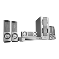
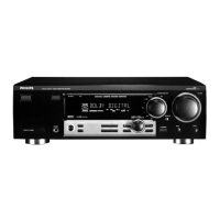
Details on model variations, features like RDS, and voltage differences.
Details on power output, distortion, frequency response, and sensitivity.
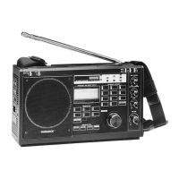
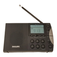
Specifies tuning range, sensitivity, and selectivity for AM/FM reception.
Covers power supply ratings, consumption, dimensions, and weight.
Provides information on remote control range, keys, and battery type.
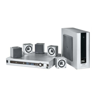
Lists specifications for front, center, and subwoofer speaker systems.
Diagram illustrating test setup for AM signal measurements.
Diagram showing test setup for FM signal measurements.
Diagram for testing auxiliary input signals.
Diagram for testing disc playback functionality.
Lists specialized tools required for servicing the unit.
Details essential equipment for handling electrostatic discharge.
Lists specific test discs used for service procedures.
Provides guidelines for safely handling and mounting chip components.
Crucial safety information regarding electrostatic discharge sensitivity.
Instructions to maintain original condition and use specified parts for safety.
Step-by-step guide for connecting speakers to the receiver.
Instructions for connecting MW and FM antennas for optimal reception.
Guides for connecting audio/video sources and recording devices.
Information on how to record digital audio signals from the receiver.
Instructions for inserting batteries into the remote control.
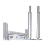
Guidance on optimizing surround sound system configuration and speaker placement.
Steps for powering on and selecting input sources for the system.
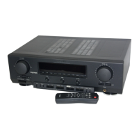
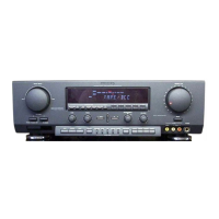
Identifies and describes the controls and connectors on the receiver's front and rear panels.
Detailed explanation of buttons and their functions on the remote control.
Flowchart for diagnosing and repairing main unit faults.
Step-by-step guide for removing the main circuit board.
Instructions for safely removing the power supply board.
Illustration showing the unit in a service position for access.
Second illustration of the unit in an alternative service position.
Internal schematic of the IC used on the key/power switch board.
Schematic representation of the key/power switch board circuitry.
Visual layout of components and traces on the PCB.
List of components used on the key/power switch board.
Schematic for the source and phone input board.
Component layout for the source and phone input board.
Schematic for the 6-channel input board.
Component layout for the 6-channel input board.
List of components for source, phone, and 6-channel input boards.
Component layout for the source and phone PCB.
Component layout for the 6-channel input PCB.
Internal schematic diagram of the ICs used on the power board.
Schematic of the power board's electrical circuits.
Component placement and routing on the power board PCB.
List of all components used on the power board.
Internal schematic of ICs used on the main board.
Schematic of the top-left section of the main board.
Schematic of the top-right section of the main board.
Schematic of the bottom-left section of the main board.
Schematic of the bottom-right section of the main board.
Component placement on the main board.
Copper layer layout of the main board.
Comprehensive list of components for the main board.
Functional block diagram of the STA308 digital audio processor.
Diagram illustrating the signal flow through the STA308.
Pinout diagram for the STA308 processor.
Detailed description of each pin's function on the STA308.
Block diagram of the 74HCT244 octal buffer/line driver.
Pin assignments for the 74HCT244 in PDIP package.
Description of each pin for the 74HCT244.
| Type | Receiver |
|---|---|
| Remote Control | Yes |
| Frequency Response | 20Hz - 20kHz |
| Outputs | 1 x RCA, 1 x 3.5mm |
| Power Output | 2 x 50W (4Ω) |
| Input Impedance | 47kΩ |