TABLE OF CONTENTS
Technical specification..........................................................2
Locartion of printed circuit boards.........................................4
Warnings & Safety................................................................5
Brief Operating Instructions ..................................................6
Dismantling Instructions......................................................15
Service hints .......................................................................24
Diagnostic Software............................................................25
Block Diagrams...................................................................59
Exploded Views ..................................................................64
Circuit Diagrams and PWB LAyouts
Control board......................................................................65
Key board left......................................................................67
Key board left 2...................................................................68
A/V Front connectors..........................................................68
Key board right ...................................................................69
Power Supply primary.........................................................71
Power Supply secondary....................................................72
Auxiliary board....................................................................75
ASP (Audio Signal Processing) board................................77
MDM (Multi-channel Decvoding Module) board .................82
Amplifier board....................................................................85
Loudspeaker Socket board.................................................90
A/V board............................................................................91
µP Sub board (CECO)........................................................99
DVIO board.......................................................................103
Digital board......................................................................112
Alignments........................................................................129
Circuit- and IC descriptions...............................................132
Abbreviations A/V-, Digital-, DVIO board..........................211
Abbreviations set related ..................................................217
Spare parts list..................................................................220
Version 1.0
LX9000R/22/25/29
Published by MS 0329 Service Audio Printed in The Netherlands Subject to modification © 3103 785 25200
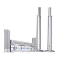
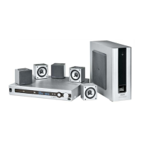
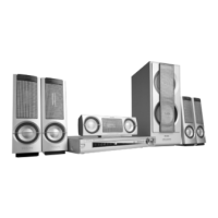
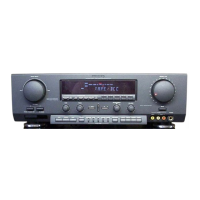
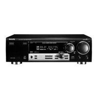
DVD+RW Receiver
©
Copyright 2003 Philips Consumer Electronics B.V. Eindhoven, The Netherlands
All rights reserved. No part of this publication may be reproduced, stored in a retrieval
system or transmitted, in any form or by any means, electronic, mechanical, photocopying,
or otherwise without the prior permission of Philips.
For servicing the DVD+RW Basic Engine we refer to
Service Manual 3122 785 12473
DVD+RW Basic Engine VAE8015, VAE8020
Only designated workshops can perform these repairs!