EasyManuals Logo

Philips LX9000R User Manual

Philips LX9000R
251 pages
To Next Page IconTo Next Page
To Previous Page IconTo Previous Page
Page #153 background imageLoading...
Page #153 background image
Circuit-, IC descriptions and list of abbreviations
EN 153LX9000R 9.
9.10.2 IC’s Analog Board
IC7408
STV6618 GENERAL OVERVIEW
1.2 Pin Description
Pin No. Symbol Description
1 Y/CVBSIN_TUN Y/CVBS Input from Tuner
2 DIGOUT3 Digital Output Pin 3
3 GND1 Ground Supply 1 for Video Inputs
4 CVBSIN_ENC CVBS Input from Encoder
5 DECV Video decoupling capacitor
6 CIN_ENC Chroma Input from Encoder
7 YIN_ENC Y Input from Encoder
8
V
CC
+5 V Power Supply for Video Inputs
9 R/PR/CIN_ENC Red or Pr or Chroma Input from Encoder
10 G/YIN_ENC Green or Y Input from Encoder
11 B/PBIN_ENC Blue or Pb Input from Encoder
12 GND2 Ground Supply 2 for Video Inputs
13 B/PBIN_AUX Blue or Pb Input from Auxiliary (SCART2 or external Cinch)
14 DIGOUT4 Digital Output Pin 4
15 G/YIN_AUX Green or Y Input from Auxiliary (SCART2 or external Cinch)
16 DIGOUT5 Digital Output Pin 5
17 R/PR/CIN_AUX Red or Pr or Chroma input from Auxiliary (SCART2 or external Cinch)
18 DIGOUT6 Digital Output Pin 6
19 Y/CVBSIN_AUX Y/CVBS Input from Auxiliary (SCART2 or external Cinch)
20 VCCB_REC Video Output Recorder Buffer Supply Pin
21 Y/CVBSOUT_REC Y/CVBS Output to Recorder
22 GNDB_REC Ground Supply for Recorder Buffer
23 COUT_AUX Chroma Output to Auxiliary (SCART2 or external Cinch)
24 VCCB1 Video Output Buffer Supply Pin
25 Y/CVBSOUT_AUX Y/CVBS Output to Auxiliary (SCART2 or external Cinch)
26 GNDB Ground Supply for Video Buffer
27 B/PBOUT_TV Blue or Pb Output to TV (SCART1 or external Cinch)
28 C_GATE External Transistor Command for Bidirectinnal B/C SCART I/O
29 G/YOUT_TV Green or Y Output to TV (SCART1 or external Cinch)
30 VCCB2 Video Buffer
31 R/PR/COUT_TV Red or Pr or Chroma Output to TV (SCART1 or external Cinch)
32 VCCB3 Video Output Buffer Supply Pin
33 Y/CVBSOUT_TV Y/CVBS Output to TV (SCART1 or external Cinch)
34 FBOUT_TV Fast Blanking Output to TV (SCART1)
35 FBIN_AUX Fast Blanking Input from Auxiliary (SCART2)
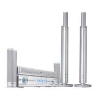
Other manuals for Philips LX9000R

Questions and Answers:

Question and Answer IconNeed help?

Do you have a question about the Philips LX9000R and is the answer not in the manual?

Philips LX9000R Specifications

Picture/Display IconPicture/Display
A/D converter10 bit, 54 MHz
Aspect ratio4:3, 16:9
D/A converter10 bit, 54 MHz
Sound IconSound
A/D converter24 bit, 96 kHz
D/A converter24 bit, 96 kHz
Distortion and Noise (1kHz)90 dB
Frequency response30-20000 Hz
Signal to noise ratio>100 dB (A-weighted)
Total Sound Power (RMS)450 W
Loudspeakers IconLoudspeakers
Satellite speaker frequency range120-20000 Hz
Satellite speaker impedance4 ohm
Center speaker frequency range120-20000 Hz
Center speaker impedance4 ohm
Subwoofer frequency range30-120 Hz
Subwoofer impedance8 ohm
Video Playback IconVideo Playback
Compression formatsMPEG1, MPEG2
Playback MediaDVD+RW, DVD+R, DVD-RW (Video mode), DVD-R, DVD-Video, SVCD, Video CD
Video disc playback systemNTSC, PAL
Video Recording IconVideo Recording
Audio compressionDolby Digital
Compression formatsMPEG2
Max recording time on DVD8 hr
Recording systemNTSC, PAL
Audio Playback IconAudio Playback
Compression formatDolby Digital, DTS, MP3, MPEG2 Multichannel, PCM
Playback MediaCD, CD-R, CD-RW, MP3-CD
MP3 bit rates32-320 kbps and VBR
Storage Media IconStorage Media
Disc capacity4.7 GB
Recording mediaDVD+R, DVD+RW
Recording speedM1, M2, M2x, M3, M4, M6, M8
Tuner/Reception/Transmission IconTuner/Reception/Transmission
Aerial Input75 ohm coaxial (IEC75)
Number of Preset Channels40
Tuner BandsFM Stereo, MW
Power IconPower
Power supply200-240 V, 50/60 Hz
Standby power consumption< 2 W

Related product manuals