EasyManua.ls Logo

Philips MC145 Service Manual

Philips MC145
24 pages
To Next Page IconTo Next Page
Page #1 background imageLoading...
Page #1 background image
Version 1.0
MC145
© 3141 785 30680
Micro System
All version
Published by YT 0605 Service Audio Printed in The Netherlands Subject to modification
©
Copyright 2006 Philips Consumer Electronics B.V. Eindhoven, The Netherlands
All rights reserved. No part of this publication may be reproduced, stored in a retrieval
system or transmitted, in any form or by any means, electronic, mechanical, photocopying,
or otherwise without the prior permission of Philips.
Handling Chip Components .......................................................... 1-1
Service Tools ................................................................................. 1-1
Leadfree and Safety Information ................................................... 1-2
Technical Specification .................................................................. 2-1
Service Measurement Setup ......................................................... 2-2
Alignment Instruction ..................................................................... 2-3
Connections and Controls ..................................................... 3-1...3-3
Disassembly Instruction ........................................................ 4-1...4-2
Set Block Diagram ........................................................................ 5-1
Set Wiring Diagram ....................................................................... 5-2
Display Board
Circuit diagram ......................................................................... 6-1
Layout diagram ........................................................................ 6-2
Combi Board
Circuit diagram (Tuner/Tape/Amp part) .................................... 7-1
Circuit diagram (CD part) ......................................................... 7-2
Layout diagram - top view ........................................................ 7-3
Layout diagram - bottom view .................................................. 7-4
Exploded View Diagram ................................................................ 8-1
Mechanical Partslist ...................................................................... 8-2
Accessories and Electrical Partslist ...................................... 9-1...9-3
TABLE OF CONTENTS

Other manuals for Philips MC145

Question and Answer IconNeed help?

Do you have a question about the Philips MC145 and is the answer not in the manual?
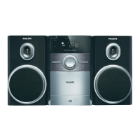
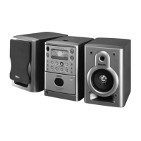
Philips MC145 Specifications

General IconGeneral
BrandPhilips
ModelMC145
CategoryStereo System
Speaker Configuration2.0
Disc PlaybackCD, MP3-CD
TunerFM
Speakers2-way
Power Supply220-240V, 50Hz

Summary

Handling Chip Components

Service Tools

Lists required tools for servicing components.

Available ESD Protection Equipment

Lists equipment to prevent electrostatic discharge damage.

Information About Lead-Free Soldering

Service Instruction and Safety

Provides instructions and safety precautions for repairs.

Product Specifications

General and Power Specifications

Details main voltage, frequency, power consumption, and dimensions.

Amplifier Specifications

Outlines output power, impedance, and frequency response.

Tuner Specifications

Lists FM and MW tuning ranges, sensitivity, and selectivity.

Cassette Recorder Specifications

Defines tape speed, wow/flutter, and frequency response.

Compact Disc Specifications

Details programming tracks, frequency response, and signal/noise ratio.

Service Measurement Procedures

Tuner Measurement Setup

Describes measurement configurations for FM and AM tuners.

CD and Recorder Measurement Setup

Outlines test setups for CD and cassette recorder functions.

Alignment Instructions

AM Alignment Procedures

Step-by-step guide for AM IF and RF alignment.

FM Alignment Procedures

Step-by-step guide for FM IF and RF alignment.

Cassette and CD Alignment

Instructions for aligning cassette head and CD functions.

Connection and Controls Overview

Remote Control Layout

Diagram showing remote control buttons and functions.

System Unit Layout

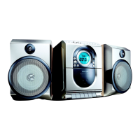
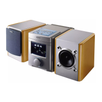
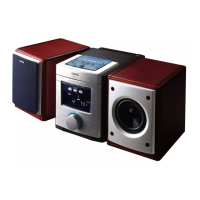
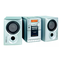
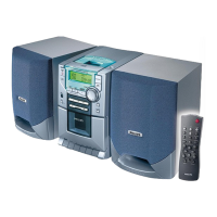
Diagram of the main system unit with numbered controls.

System and Remote Controls Description

Controls Description

Detailed explanation of system and remote control functions.

Preparations and Connections

Rear Panel Connections

Guide to connecting power, speakers, and antenna.

Speaker Connection Details

Specific instructions for connecting front speakers.

Disassembly Instructions - Top and CD Module

Remove Top Cabinet

Steps to remove the main top cabinet cover.

Remove CD Module and Cover

Procedures for accessing and removing the CD module.

Disassembly Instructions - Internal Components

Remove CDM, Back Cabinet, and PCB Bracket

Steps for removing internal structural and PCB components.

Remove Cassette Board and Front PCB Assembly

Procedures for removing tape deck and front panel electronics.

Set Block Diagram

Set Wiring Diagram

Circuit Diagram - Display Board

Layout Diagram - Display Board

Circuit Diagram - Combi Board (Tuner/Tape/Amp)

Circuit Diagram - Combi Board (CD Part)

Layout Diagram - Combi Board (Top View)

Layout Diagram - Combi Board (Bottom View)

Exploded View Diagram

Mechanical Parts List

Accessories and Electrical Parts

Display Board Electrical Parts List

List of electrical components for the display board.

Record Board Electrical Parts List

List of electrical components for the record board.

Electrical Parts List - Main Board

Electrical Parts List - Main Board (Continued)

Miscellaneous Electrical Parts

List of miscellaneous electrical components and accessories.

Related product manuals