Do you have a question about the Philips MCM700/12 and is the answer not in the manual?
Detailed specifications for the amplifier section.
Specifications related to the CD playback function.
Technical details for the radio tuner function.
Specifications for USB playback capabilities.
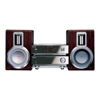
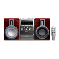
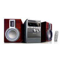
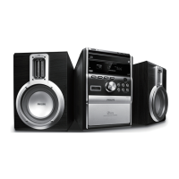
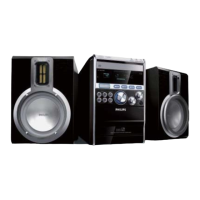
Physical dimensions of the included speakers.
General power and dimension details for the system.
Measurement setup for FM tuner functionality.
Measurement setup for AM tuner functionality.
Measurement setup for CD player functionality.
Precautions regarding electrostatic discharge during repair.
Guidelines for handling lead-free soldering processes.
Procedures for returning the system to original condition after repair.
Procedures for checking CD disc compatibility and playback.
Guidance for customers about checked sets with no faults.
Method for cleaning the CD lens using a dry brush.
Method for cleaning the CD lens using cleaning fluid.
Measuring the signal for jitter on the CD player.
Measuring the laser current of the CD drive.
Measuring CD drive photodiode offsets and compensation.
Connecting the AC power cord and other rear connections.
Connecting speakers and the DAB/FM antenna.
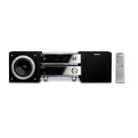
Instructions for initial remote control use and battery replacement.
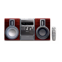
Overview of system buttons and remote control functions.
Notes for operating the remote control effectively.
Lists common issues and their corresponding solutions.
Steps to remove the bottom cover of the CD part.
Steps to remove the back panel of the CD part.
Steps to remove the side panels of the CD part.
Steps to remove the top cabinet of the CD part.
Steps to remove the front cabinet of the CD part.
Steps to remove the display board assembly.
Steps to remove the bottom cover of the tuner and amp part.
Steps to remove the back panel of the tuner and amp part.
Steps to remove the side panels of the tuner and amp part.
Steps to remove the top cabinet of the tuner and amp part.
Steps to remove the front cabinet of the tuner and amp part.
Procedure to check software version for CD/MP3 playback.
Procedure to check the CPU software version.
Steps for upgrading system software via disc or USB.
Exploded view illustrating the assembly of the amplifier section.
Exploded view illustrating the assembly of the CD player section.
List of electrical components for the pre-amplifier board.
List of electrical components for the headphone PCB.
List of electrical components for the volume control PCB.
List of electrical components for the output PCB.
List of electrical components for the main amplifier PCB.
List of electrical components for the door switch PCB.
List of electrical components for the lamp PCB.
List of electrical components for the push key PCB.
List of electrical components for the switch PCB.
List of electrical components for the display PCB.
List of electrical components for the CPU PCB.
List of electrical components for the servo PCB.
Initial release of the service manual.
Revision including CD playability and diagram updates.
Revision updating AMP Board diagrams.
Revision updating software check and diagrams.
Revision updating mechanical parts list.
Revision updating electrical parts list.
| Audio Formats Supported | MP3, WMA |
|---|---|
| Tuner | FM |
| Bluetooth | Yes |
| USB Direct | Yes |
| Radio | FM |
| Remote Control | Yes |
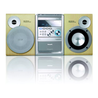
| Type | Micro Hi-Fi System |
| Disc Playback | CD |
| Connectivity | Bluetooth, USB |
| Speakers | 2 speakers included |