Do you have a question about the Philips MCM700 and is the answer not in the manual?
Detailed technical specifications for the system's components.
Guidelines and diagrams for measuring system performance.
Information on service tools, ESD, and lead-free soldering.
Step-by-step instructions for diagnosing CD playback issues.
Instructions for initial setup and operation of system controls.
Solutions for common operational problems and remote control issues.
Step-by-step guides for disassembling CD and Tuner/Amp parts.
Procedure to check and update system software versions.
Overall system block diagram showing component interconnections.
Detailed wiring diagram of the system.
Circuit diagram for the VFD/Key board assembly.
Layout diagram for the VFD/Key board assembly.
Circuit diagram for the CD block.
Layout diagram for the CD block.
Circuit diagram for the Tuner board.
Layout diagram for the Tuner board.
Circuit diagram for the Servo/MPEG Decoder Card.
Layout diagram for the Servo/MPEG Decoder Card.
Circuit diagrams for the amplifier blocks (AMP, Pre-AMP, HP/Volume).
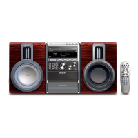
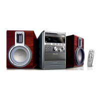
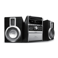
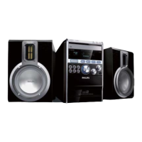
Visual representation of components for assembly/disassembly.
List of mechanical and accessory parts with part numbers.
List of electrical components and their part numbers.
List of updates and revisions to the service manual.
| output power | 2x80W RMS, 2x160W Music Power |
|---|
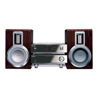
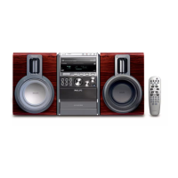
| main speaker | 2 way, 4" woofer, Bass Reflex Speaker System, Speaker grilles detachable, Piezo tweeter |
|---|
| station presets | 40 |
|---|---|
| tuner bands | FM Stereo |
| aux in | 2x(L/R)/ RCA |
|---|---|
| headphone | 3.5 mm |
| usb | USB host |
| power supply | 220-240V, 50Hz |
|---|---|
| eco power standby | 1 watt |
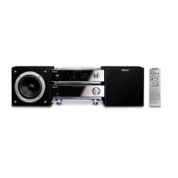
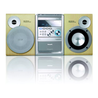
| set dimensions | 208 x 156 x 268 mm |
|---|---|
| main speaker dimensions | 145 x 230 x 215 mm |
| packaging dimensions | 475 x 275 x 330 mm |