3-2
SERVICE POSITIONS
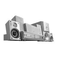
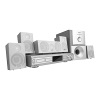
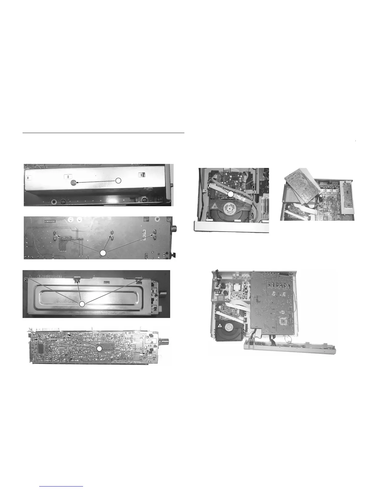
Service position A
Loosen 4 screws "K" to remove the DVD module as shown
below
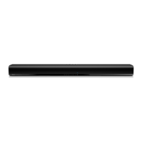
Service position C
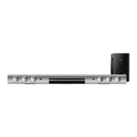
Service position B
Note: In some service positions the components or copper patterns of one board may risk touching its neighbouring pc
boards or metallic parts. To prevent such short-circuit use a piece of hard paper or other insulating material between them.
3-2
K
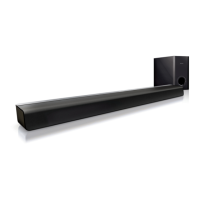
Dismantling of the Tuner PCB
1) Loosen 1 screw "G" and 3 solder points "H" to remove the
sheild cover.
2) With the Main Board already dismantle, remove the
Tuner board / sheild bracket assembly by unsolder the
wire connector and 6 points "H".
Figure 9
G
Figure 10
I
Figure 11
J
Figure 12
3) Separate the Tuner board by unsoldering 4 points "J".
H