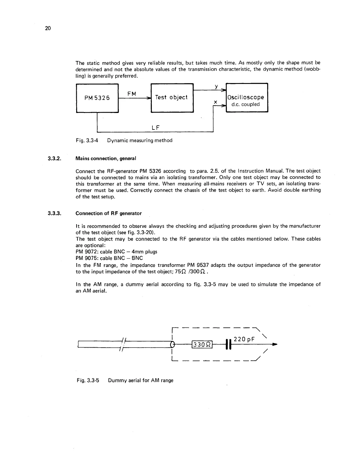
The static method gives very reliable results, but takes much time. As mostly only the shape must be
determined and not the absolute values of the transmission characteristic, the dynamic method (wobb-
ling) is generally preferred.
PM
5326
Oscilloscope
Fig.
3.3-4
Dynamic measuring method
3.3.2.
Mains connection, general
Connect the RF-generator PM
5326
according to para.
2.5.
of the Instruction Manual. The
test
object
should be connected to mains via an isolating transformer. Only one
test
object may be connected to
this transformer at the same time. When measuring all-mains receivers or TV
sets,
an isolating trans-
former must be used. Correctly connect the chassis of the
test
object to earth. Avoid double earthing
of the test setup.
3.3.3.
Connection of
RF
generator
It
is
recommended to observe always the checking and adjusting procedures given by the manufacturer
of the test object (see fig.
3.3-20).
The
test
object may be connected to the RF generator via the cables mentioned below. These cables
are optional:
PM
9072:
cable BNC
-
4mm plugs
PM
9075:
cable BNC
-
BNC
In the FM range, the impedance transformer PM
9537
adapts the output impedance of the generator
to the input impedance of the
test
object;
75R /300n.
In the AM range, a dummy aerial according to fig.
3.3-5
may be used to simulate the impedance of
an AM aerial.
Fig.
3.3-5
Dummy aerial for AM range