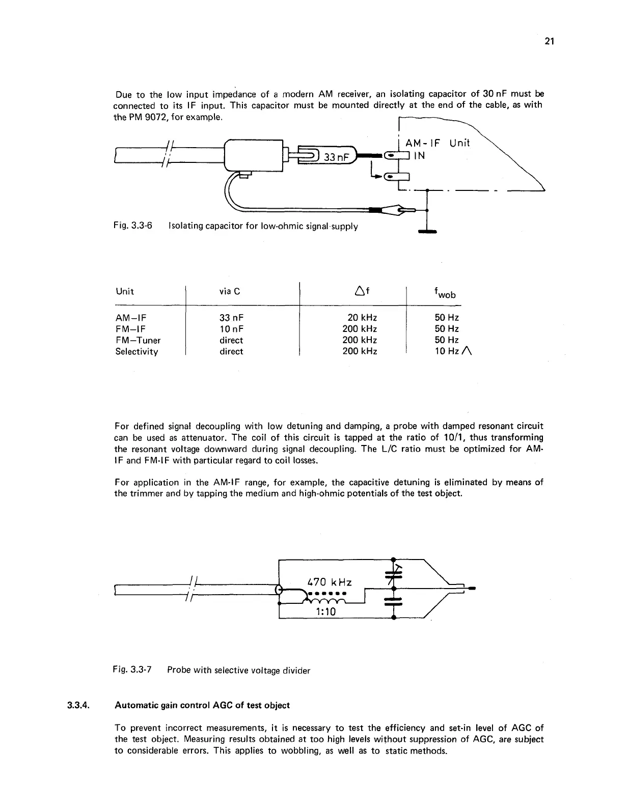
Due to the low input impedance of
a
modern AM receiver, an isolating capacitor of 30 nF must
be
connected to
its
IF input. This capacitor must be mounted directly at the end of the cable, as with
the PM 9072, for example.
I::
---
Fig. 3.3-6
Isolating capacitor for low-ohmic signal.supply
For defined signal decoupling with low detuning and damping, a probe with damped resonant circuit
can be used as attenuator. The coil of this circuit
is
tapped
at
the ratio of 1011, thus transforming
the resonant voltage downward during signal decoupling. The L/C ratio must be optimized for AM-
IF and FM-IF with particular regard to coil losses.
For application in the AM-IF range, for example, the capacitive detuning
is
eliminated by means of
the trimmer and by tapping the medium and high-ohmic potentials of the test object.
Unit
AM-IF
FM-IF
FM-Tuner
Selectivity
Fig. 3.3-7
Probe with selective voltage divider
via
C
33 nF
10 nF
direct
direct
A
f
20 kHz
200 kHz
200 kHz
200 kHz
3.3.4.
Automatic gain control
AGC
of test object
fwob
50
Hz
50 Hz
50 Hz
IOHZA
To prevent incorrect measurements,
it
is
necessary to test the efficiency and set-in level of AGC of
the test object. Measuring results obtained at too high levels without suppression of AGC, are subject
to considerable errors. This applies to wobbling,
as
well as to static methods.