It
is
common practice to adequately fix the sliding DC voltage of AGC to a constant DC voltage from
a low-ohmic source. This can
be
achieved by an adjustable DC supply
(e.
g.
PE
1535 or
PE
15371,
if the controlling DC voltage of the
test
object
is
related only to the chassis without being isolated.
In case of conductive hum-pickup, it
is
recommended to use a dry battery or an accumulator and to
tap the voltage by means of
a
potentiometer connected in parallel to the battery. The output of such
a potentiometer circuit becomes more low-ohmic with moderate battery load, if the potentiometer
is
followed by a transistor ermitter-follower stage.
The connection point and the voltage level to be set are given in the checking and adjusting procedures
of the test object. Receivers with suppressed (delayed) control set-in point produce acceptable measur-
ing values, when working below the set-in point during measurement, so that the control is not
effective.
3.3.5.
Type and connection of indicator
The following indicators can
be
used: multi-purpose instruments, calibrated signal tracers, selective
pV- or mV-meters, broadband voltmeters, oscilloscopes, wobble indicators and x/y recorders.
3.3.5.1.
Connection to
LF
output
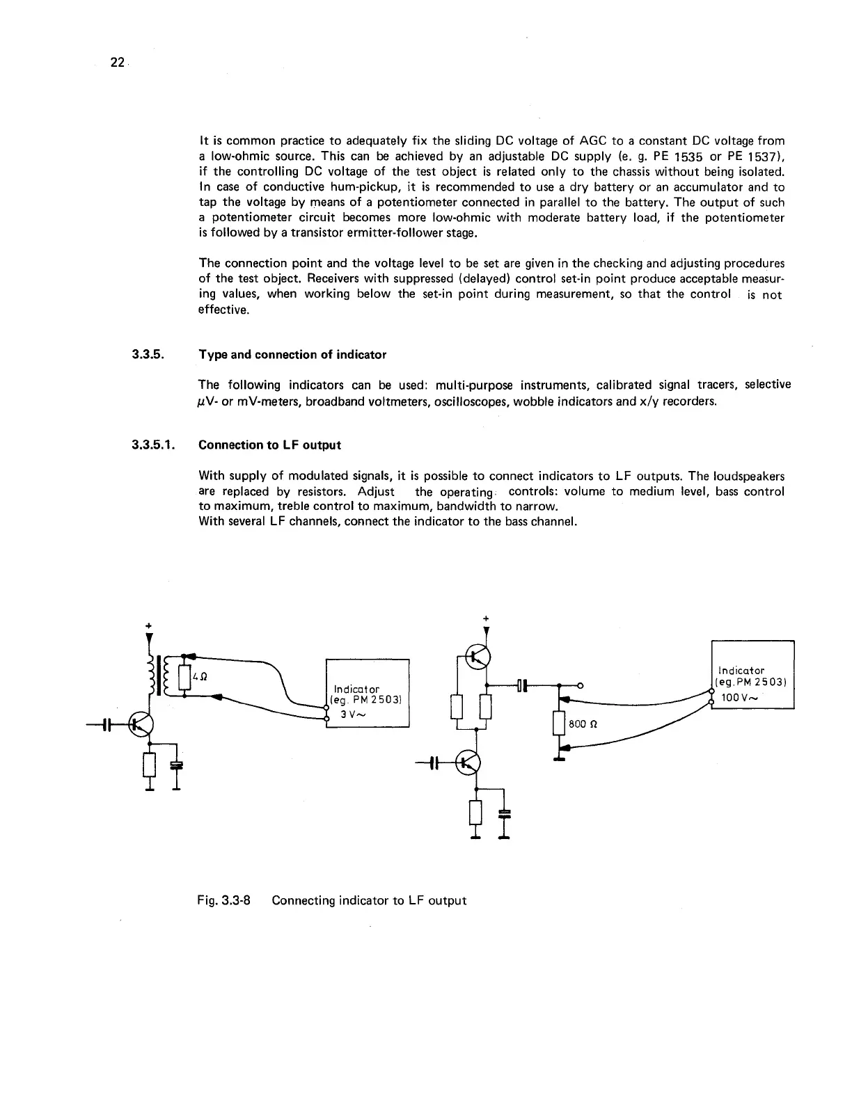
With supply of modulated signals,
it
is
possible to connect indicators to
LF
outputs. The loudspeakers
are replaced by resistors. Adjust the operating controls: volume to medium level, bass control
to maximum, treble control to maximum, bandwidth to narrow.
With several
LF
channels, connect the indicator to the bass channel.
)I@---l
(eg
PM
2503)
Fig. 3.3-8
rl
Indicator
Connecting indicator to
LF
output