25
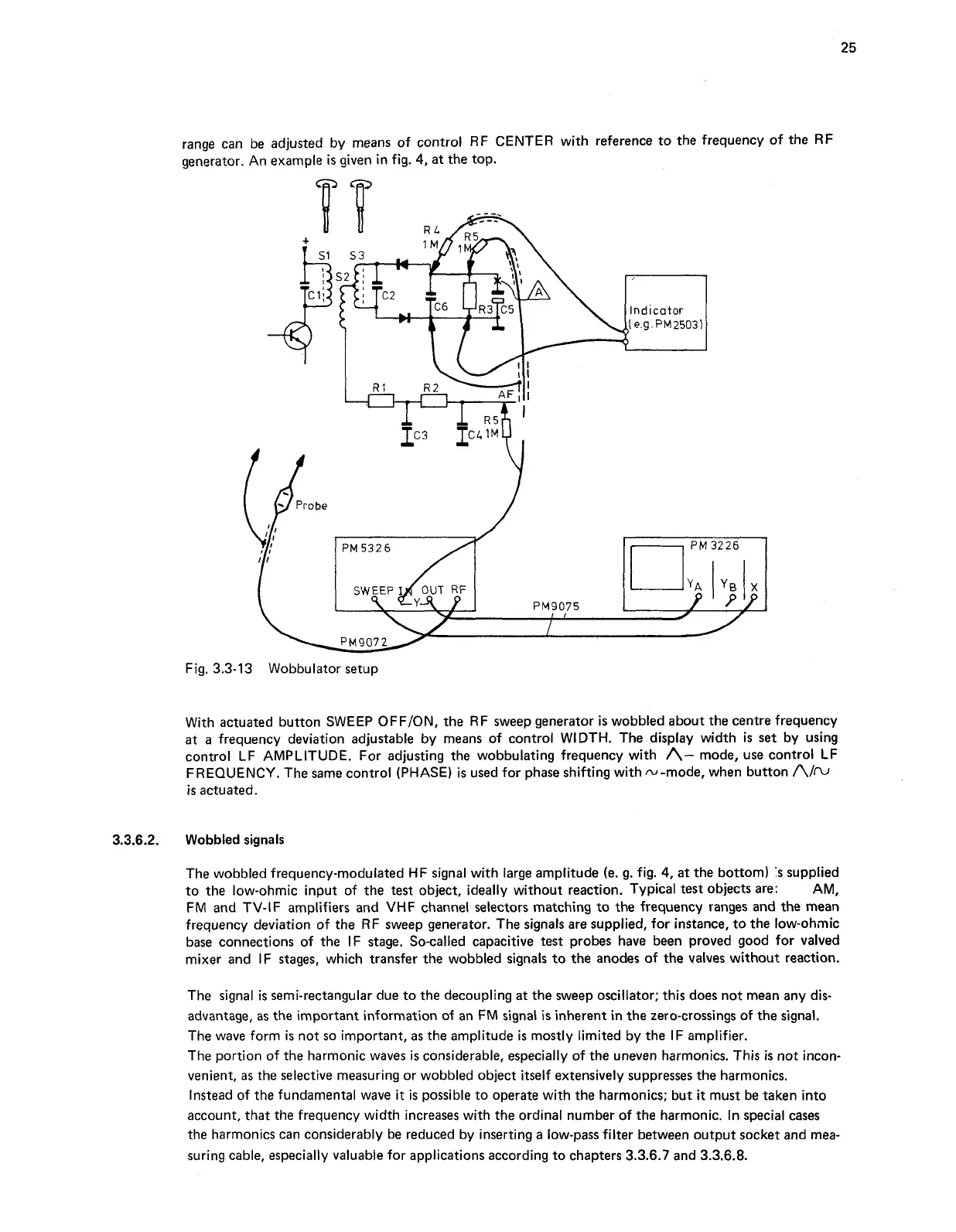
range can be adjusted by means of control RF CENTER with reference to the frequency of the RF
generator. An example
is
given in fig.
4,
at the top.
Fig. 3.3-13 Wobbulator setup
With actuated button SWEEP OFFION, the RF sweep generator
is
wobbled about the centre frequency
at
a
frequency deviation adjustable by means of control WIDTH. The display width
is
set
by using
control LF AMPLITUDE. For adjusting the wobbulating frequency with
A-
mode, use control LF
FREQUENCY. The same control (PHASE)
is
used for phase shifting with N-mode, when button
Aim
is
actuated.
3.3.6.2.
Wobbled signals
The wobbled frequency-modulated HF signal with large amplitude (e. g. fig.
4,
at the bottom)
's
supplied
to the low-ohmic input of the
test
object, ideally without reaction. Typical test objects are:
AM,
FM and TV-IF amplifiers and VHF channel selectors matching to the frequency ranges and the mean
frequency deviation of the RF sweep generator. The signals are supplied, for instance, to the low-ohmic
base connections of the IF stage. So-called capacitive
test
probes have been proved good for valved
mixer and IF stages, which transfer the wobbled signals to the anodes of the valves without reaction.
The signal
is
semi-rectangular due to the decoupling at the sweep oscillator; this does not mean any dis-
advantage,
as
the important information of an FM signal
is
inherent in the zero-crossings of the signal.
The wave form
is
not so important,
as
the amplitude
is
mostly limited by the IF amplifier.
The portion
of
the harmonic waves is considerable, especially of the uneven harmonics. This
is
not incon-
venient,
as
the selective measuring or wobbled object itself extensively suppresses the harmonics.
Instead of the fundamental wave it
is
possible to operate with the harmonics; but
it
must be taken into
account, that the frequency width increases with the ordinal number of the harmonic. In special cases
the harmonics can considerably be reduced by inserting a low-pass filter between output socket and mea-
suring cable, especially valuable for applications according to chapters 3.3.6.7 and 3.3.6.8.