The X-channels of wobble indicators,
oscilloscopes, special wobble displays or X
-
Y high-speed recorders must be DC-coupled. Otherwise,
linearity errors occur in X-direction, particularly with slow wobbulating frequencies.
Finite lower limit frequencies in the Y-channel cause pulse droops due to suppression of the DC com-
ponents. In this way, an error is simulated, which
is
actually not present. The upper limit frequency of
the Y-channel has less effect, as the Y-signal
is
decoupled after the demodulator and is therefore at low
frequency. The oscillograms show that the leading and trailing edges are not very steep.
The non-linearity of an X-channel with finite lower limit frequency
is
reducible, when wobbled with
sine-waves at mains frequency.
As the edges of the wobbling sine-signal are not linear, wobbling must be symmetric to the zero-axis
crossing to obtain a deflection synchronous and in phase with the sinusoidal frequency variation. This
is the case, when the sweep-flyback
is
made coincident by means of control PHASE.
AGC
of wobbled object
For suppression of AGC of the wobbled object, see para.
3.3.4.
The DC supplies PE
1535
or PE
1537
are suited for this purpose.
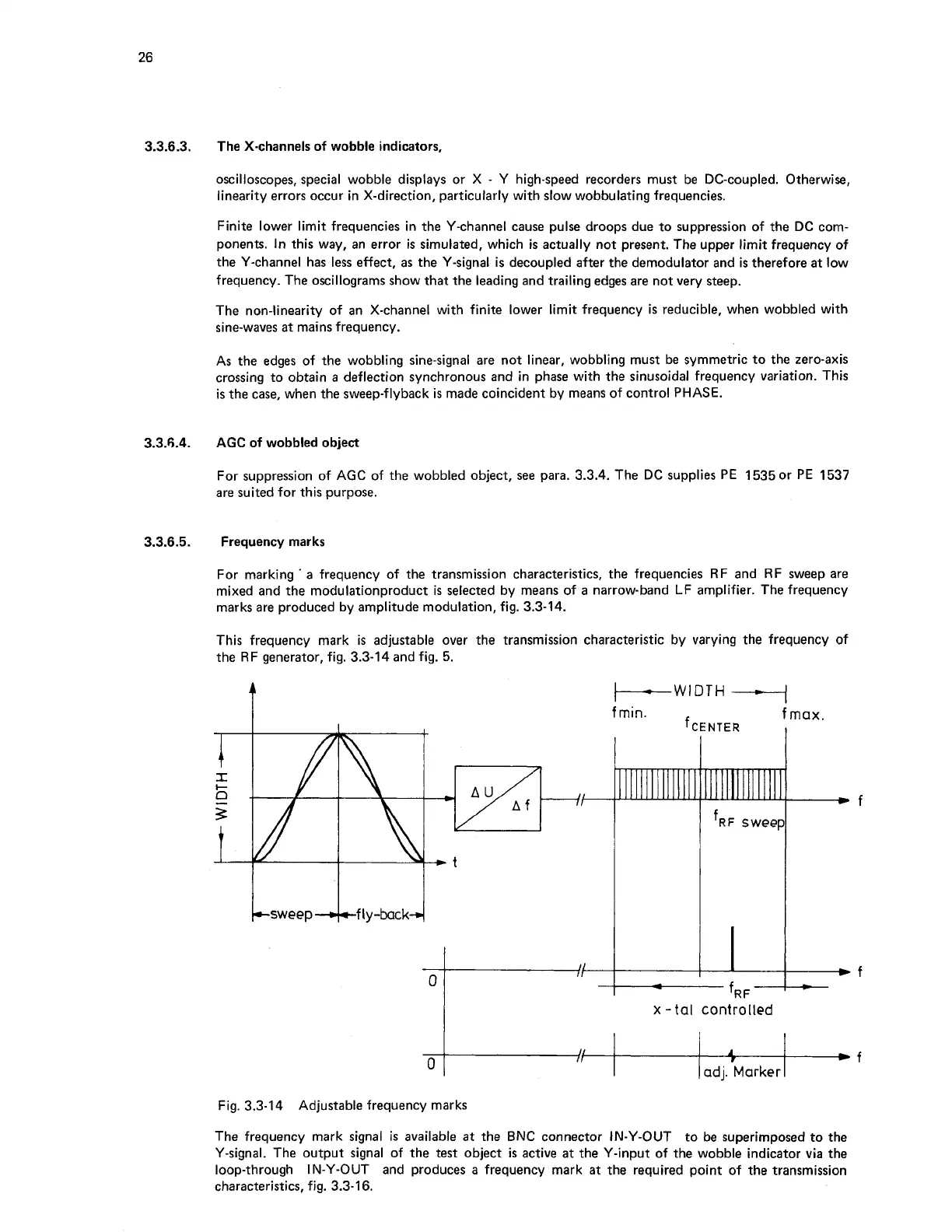
Frequency marks
For marking
'
a frequency of the transmission characteristics, the frequencies RF and RF sweep are
mixed and the modulationproduct is selected by means of a narrow-band LF amplifier. The frequency
marks are produced by amplitude modulation, fig.
3.3-14.
This frequency mark is adjustable over the transmission characteristic by varying the frequency of
the RF generator, fig.
3.3-14
and fig.
5.
f
min.
f
max
CENTER
,
A
-
~RF
-
x
-
tal
controlled
A
*
f
adj. Marker
Fig.
3.3-14
Adjustable frequency marks
The frequency mark signal
is
available at the BNC connector IN-Y-OUT to be superimposed to the
Y-signal. The output signal of the test object is active at the Y-input of the wobble indicator via the
loop-through IN-Y-OUT and produces a frequency mark at the required point of the transmission
characteristics, fig.
3.3-1
6.