The frequency mark can be displayedseparatelyor in addition via the second channel of
a
wobble indi-
cator, fig. 3.3-1 7 (LH-side).
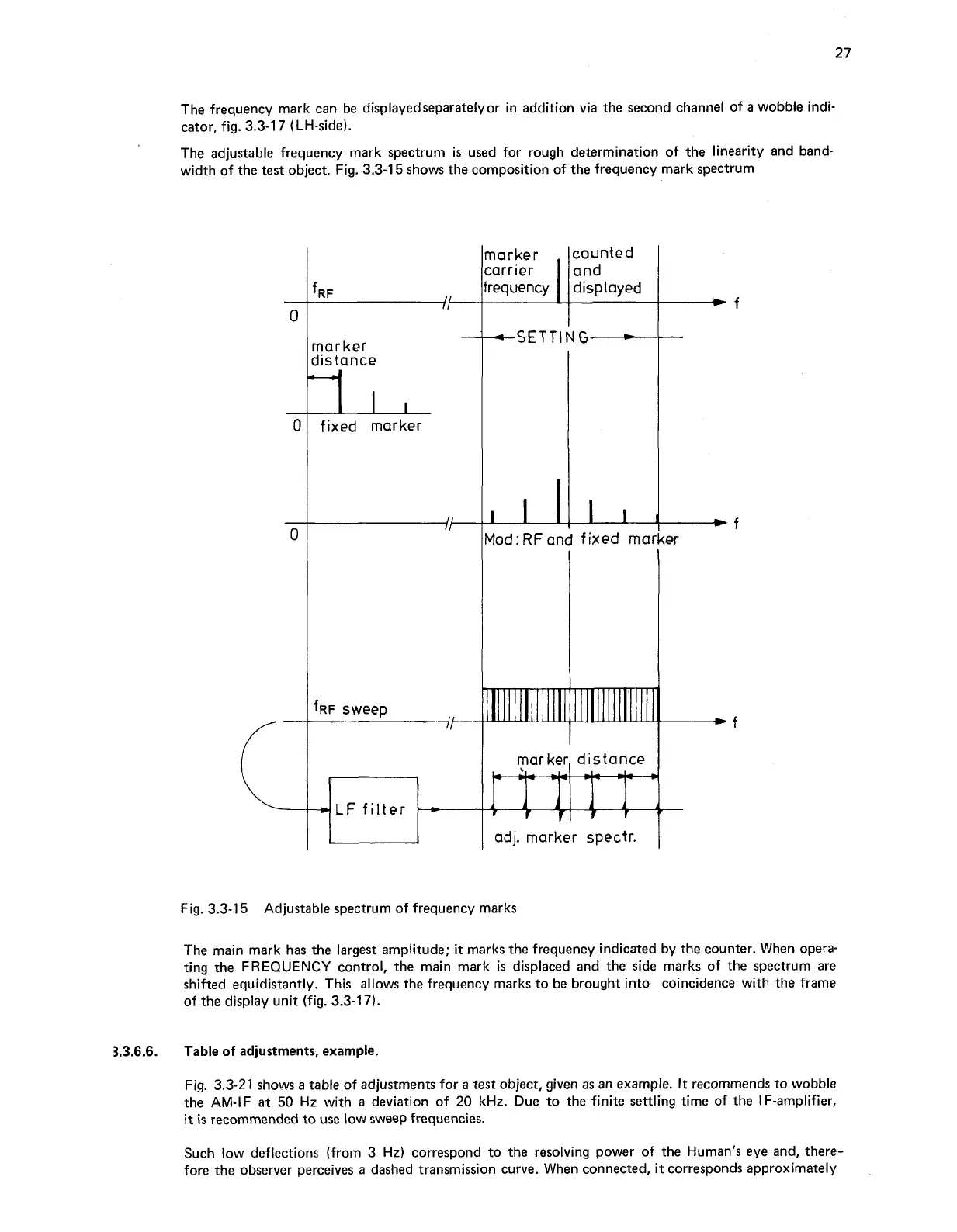
The adjustable frequency mark spectrum is used for rough determination of the linearity and band-
width of the
test
object. Fig. 3.3-1
5
shows the composition of the frequency mark spectrum
-
marker
distance
-II,
fixed marker
F
sweep
/I---
LF
filter
G
lad
:
RF
and
fixed
mar
marker, distance
adj.
marker spectr.
Fig. 3.3-1
5
Adjustable spectrum of frequency marks
The main mark has the largest amplitude;
it
marks the frequency indicated by the counter. When opera-
ting the
FREQUENCY
control, the main mark
is
displaced and the side marks of the spectrum are
shifted equidistantly. This allows the frequency marks to be brought into coincidence with the frame
of the display unit (fig. 3.3-17).
3.3.6.6.
Table
of
adjustments, example.
Fig. 3.3-21 shows a table of adjustments for a test object, given as an example.
It
recommends to wobble
the AM-IF
at
50 Hz with a deviation of 20 kHz. Due to the finite settling time of the IF-amplifier,
it
is
recommended to use low sweep frequencies.
Such low deflections (from 3 Hz) correspond to the resolving power of the Human's eye and, there-
fore the observer perceives
a
dashed transmission curve. When connected,
it
corresponds approximately