3.3.6.7.
S-characteristic of an
FM
demodulator
The quality of the receptidn
depends considerably on the zero-axis crossing, symmetry and linearity
of the S-characteristic of an FM demodulator. Fig.
3.3-17
shows the properly adjusted S-characteristic
of a ratio detector with frequency marks and an oscillogram with frequency marks on the zero line.
These frequency marks considerably facilitate the adjustment and evaluation of the demodulator cha-
racteristic, particularly when the marks are spaced at the same distance as the reference frame.
For adjusting the S-characteristic, supply the wobbled RF signal to the base of the last FM-IF transistor
stage, so that the IF amplifier cannot reduce the bandwidth.
3.3.6.8.
S-characteristic of a coincidence demodulator
Fig.
3.3-1
8
shows the transmission characteristic of an IF quadrature demodulator (coincidence demo:
dulator).
It
can be realized by an IC with high amplification and strict limitation of the main IF signal
a. o. The main channel selection acts as a filter between the FM tuner and the IF quadrature demodu-
lator.
A
parallel resonant circuit can
be
used as phase shifter, furnishing a phase-shifted voltage component
with high-ohmic IF signal control, which
is
proportional to the frequency variation. For the centre fre-
quency, the phase shift is
90'.
For demodulation, the main signal is multiplied by the phase-shifted voltage in a multiplier. The plotted
geometric sums give the transmission characteristic.
3.3.6.9.
Amplitude limitation
For checking the amplitude limitation of the test object, the wobbled RF signal
is
additionally amplitude-
modulated with button MODULATION OF F/ON depressed.
Set attenuator to position
40
dB and reduce the RF signal by means of potentiometer
0
-
80
dB just
until the superposition of the
1
kHz signal over the S-characteristic becomes visible. Then turn the attenu-
ator switch to position
3
dB or
0
dB; with correct amplitude limitation, the superposition of the
S-characteristic should be completely suppressed. When increasing the signal, take care that the set-in
point of the AGC
is
not exceeded, otherwise additional limitation could be the result, see para.
3.3.4
and fig.
3.3-19.
3.3.7.
l
F transmission characteristic of a
TV
set
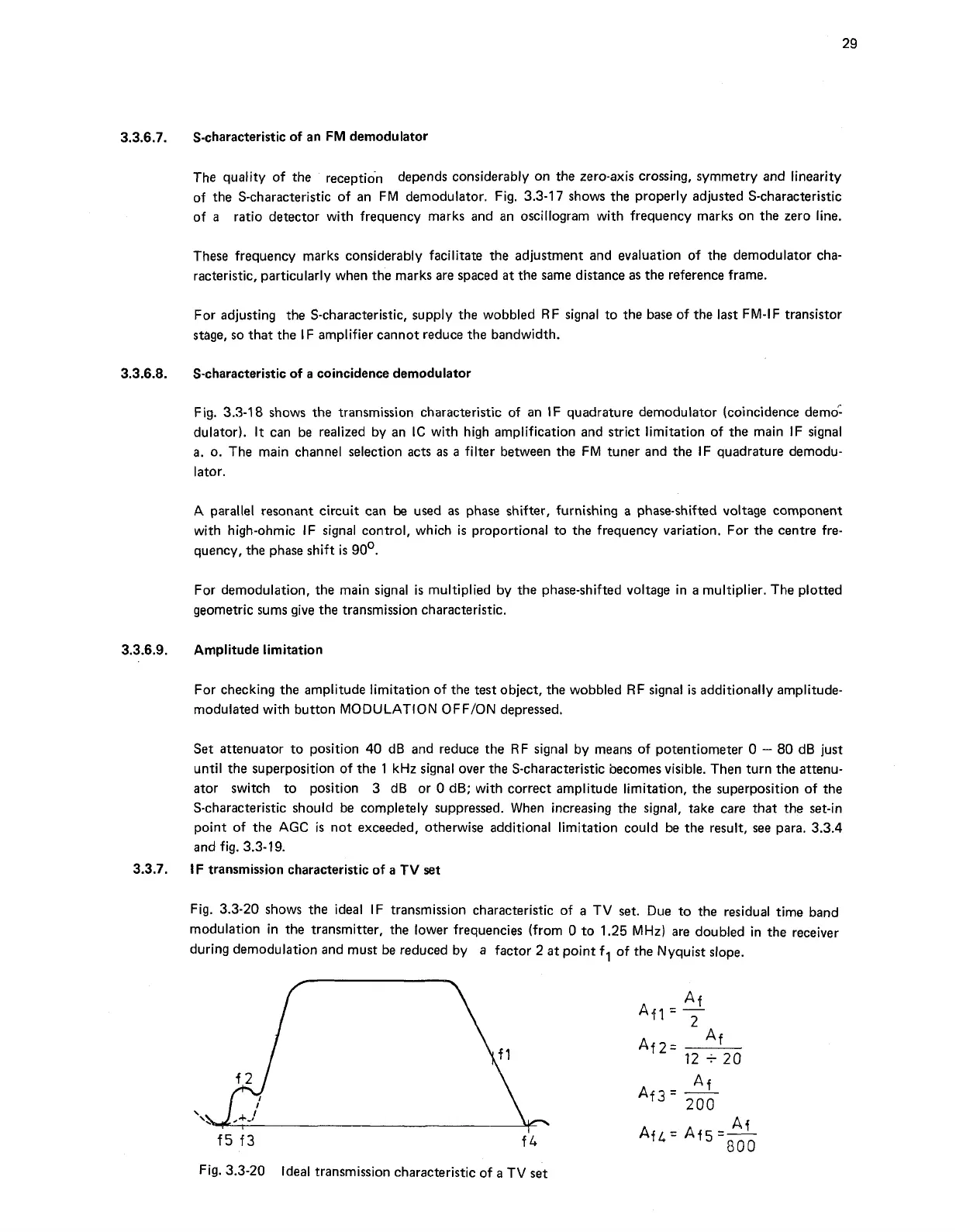
Fig.
3.3-20
shows the ideal IF transmission characteristic of a TV set. Due to the residual time band
modulation in the transmitter, the lower frequencies (from
0
to
1.25
MHz) are doubled in the receiver
during demodulation and must be reduced by a factor
2
at point
fl
of the Nyquist slope.
Fig.
3.3-20
Ideal transmission characteristic of a TV
set