The amplitude
of the waveform at f2 should
be
12 to 20 times smaller than the max. amplitude of
the vision. With parallel sound mode, the amplitude
is
reduced 20 times
at
point f3. The suppression
factor of the adjacent picture f5 and the adjacent sound f4 should
be
800
at
least.
Refer to manufac-
turer's documentation for exact alignment procedure.
/
To determine the adequate damping of the critical points of the transmission characteristic,
e.
g. f2,
f3, f4 and f5 in fig. 3.3-20, the point-by-point method
is
recommended.
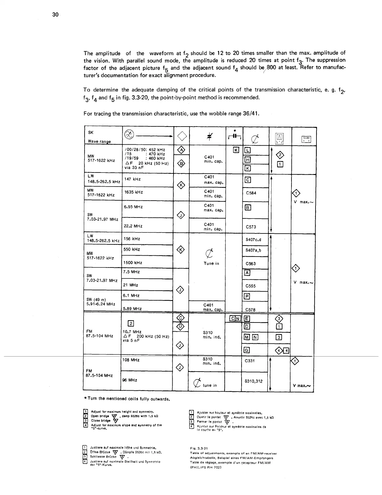
For tracing the transmission characteristic, use the wobble range 36/41.
SK
Wave range
-
0
1
/00/28/50: 452
kHz
1
A
via
33
nF
148.5-262.5
kHz
147
kHz
517-1622
kHz
1635
kHz
I
1
6.95
MHz
SW
7.03-21.97
MHz
22.2
MHz
I
1
LW
148.5-262.5
kHz
1
kHz
550
kHz
MW
517-1622
kHz
1
1500
kHz
I
7.5
MHz
SW
7.03-21.97
MHz
-
C401
min. cap.
C401
max,
cap.
C401
min. cap.
C401
max.
cap.
C401
min. caD.
@
Tune in
10.7
MHz
min.
~nd.
vla
5
nF
108
MHz
S310
min.
ind.
FM
37.5-104
MHz
96
MHz
@
tune
in
*Turn the mentioned coils fully outwards.
Aluster
Pur
hauteur et ~ymAtr10 maximales.
Ouvrir 18 ponlet
.
Amorllr S525c
avac
1,s
kfl
Femer la pontet
.
AjJs!rr
sur
Fieideur
el Sym6trle maximales de
la
CIU~~F
erg
"S".
Jcsllere
auf
maximale llEhe
unJ
Symmetrle.
Jurtiere ad rnaxlmale Steilheil
und
SyvncIric
der
"3'-Kurve.
Fig.
3.3-21
Table
of
adjustments, example
of
an
FM/AM-receiver
Abgleichfabelle, Beispiel einer FM/AM-Empfangerr
Table
de
reglage, exempie
d'un
Iecepteur
FMIAM
(PHILIPS RH
702)