The AM modulator is represented by the
4
quadrant multiplier
IC
356
of unit
4.
When unmodulated the carrier is determined by a d.c. voltage
of input
4.
NF modulation is possible with amplitude of equal value as
this d.c. voltage; so
100%
modulation is possible. Potmeter
634
adjusts
the transmission characteristic to maximum
NF
suppression.
The
1
kHz
oscillator,
IC
354
of unit
6
produces the sinewave signal
for internal modulation. External modulation is possible via buffer
stage
308.
Amplitude, automatic gain control
AGC
The RF signal signal at
IC
355.7
is rectified and amplified (transistors
306,
311)
and fed to the control input of
354.5.
Time constant
(649
+
644)/522 effects amplitude modulations of s20
Hz
not being gain controlled.
The amplitude is adjusted by potmeter
645.
The output amplifier is built up as impedance converter in cascode
stage 307, 308,resulting in maximum bandwidth. During retrace in the sweep
mode diode
406
closes transistor
308
cutting off the RF signal, see
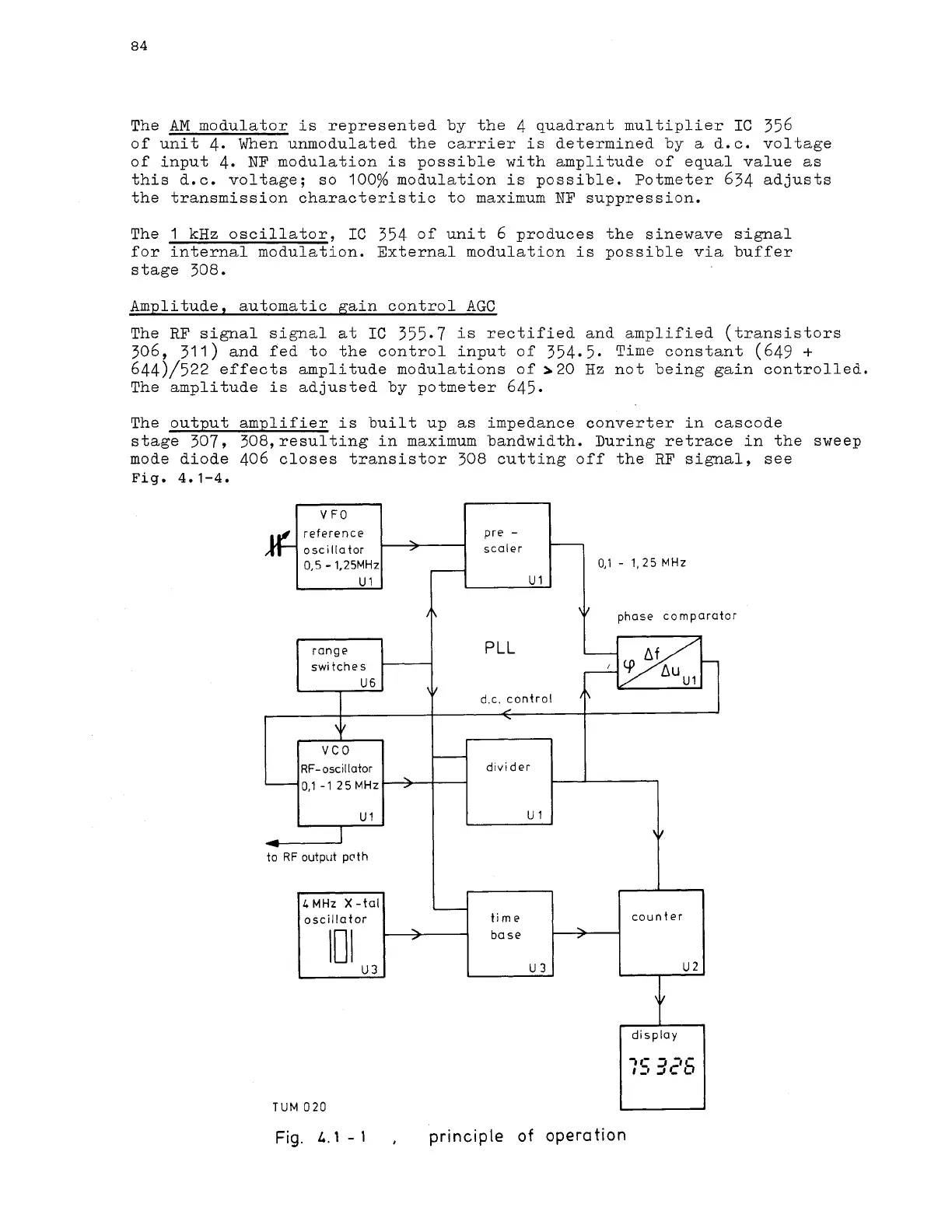
Fig.
4.1-4.
reference
oscillator scaler
0,5
-
1,25MHz
0,l
-
1,
25 MHz
+
phase comparator
range
d.c. control
to
RF
output pcth
I I
1
display
7C
3
-1-
1-1
AC~
n
-
1
TUM
020
u
:
-
divider
-
Fig.
L.
1
-
1
,
principle of operation
VCO
RF-oscillator
0,t
-1
25
MHz
counter
U
2
I
\
,
LMHz
X-tal
oscillator
101
U
3
-
'
time
base
U
3