36
.
3.5.
CHECKING AND ADJUSTING
Tolerances given in this
chapter apply only in case
of newly adjusted instruments. The
values
may
differ from
those given in chapter 1.2. Technical data.
The adjusting
elements,
their
location and function
are mentioned in chapter 3.4.
Any adjustment,
maintenance, and repair of an instrument
which is opened
whilst
connected to
the mains
should be avoided as far as possible and, if
inevitable,
shall
be
only carried out by skilled
personnel familiar
with the
risk of shock involved.
3.5. 1 .
General test
3.5. 1. 1. Power
supply
—
Check that the current consumption is < 20
mA at 220 V mains,
50 Hz.
—
Check that the filtered voltage across
capacitor 528 lies
between
+19 V and
+22
V; and across
capacitor
531 between
—19
V
and
—22
V (mains
voltage 220 V).
—
Check that the
stabilized voltage across
capacitor 530 lies
between
+1
3.6
V and
+15.4 V and across
capacitor 533 between
—13.6
V
and
—15.4
V.
—
Check that the filtered voltage
for DC-operation
across capacitor
527
is
1.4 V
±
0.2 V
(mains voltage 220
V)
—
Depress button R
-
Check the polarity of test
sockets l-E
—
Depress
button
C
—
Connect an external voltage to
sockets DC-BIAS
-
Check the polarity of
test sockets l-E
3.5. 1. 2. Oscillator
—
Frequency check:
button D not depressed;
f
=
970 Hz
±
19 Hz
button D
depressed; f
=
97
Hz
±
2 Hz
—
Set
range switch to position 10
nF
-
Depress button C
—
Measure the amplitude, at 100
Hz and 1 kHz,
between points 7
and 11 of
push-button switch 801A.
Right value:
between 650 and 800 mV
rms
.
—
Set range
switch to position
1
juF
-
Check that the amplitude, at
1 kHz, is 1/10
of the value measured
with range switch
in position xIO
nF
(measure also between points 7
and 11)
-
Supply a
voltage of 7 V
rms
to sockets
EXT.-AC of the
bridge
—
Check the amplitude
between points 801 A/7
and 801 A/1 1 at 100
Hz; 5 kHz and
20 kHz.
Right value:
between 600 and 750 mV
rms
3.5. 1.3. Indication
amplifier
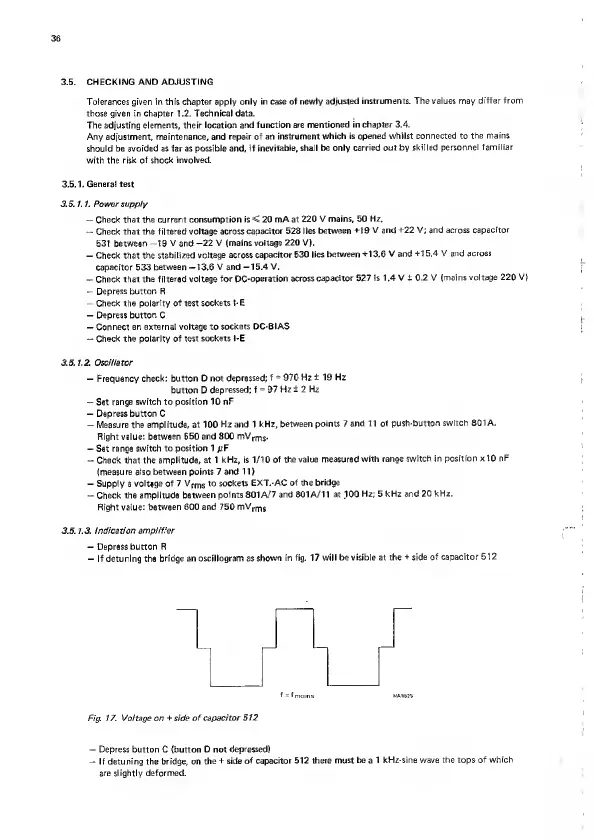
—
Depress button R
—
If detuning the
bridge an oscillogram as
shown in fig. 17
will be visible at the
+ side of capacitor 512
f
=
fnroins. MA8825
Fig 17.
Voltage
on
+ side of capacitor
512
—
Depress button C (button D
not depressed)
If detuning the bridge, on
the
+
side
of capacitor 512
there must be a 1 kHz-sine wave
the
tops
of which
are slightly deformed.