38
3.5.24. Q/D potentiometer
—
Turn the Q/D potentiometer to
left-hand
stop
—
Check that the mark on the control knob coincides
with the mark
on
the text plate
—
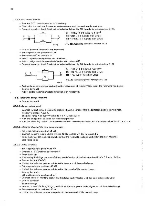
Connect to
sockets
I and
E
a
circuit
as
indicated below (fig. 19) in
order
to adjust resistor 712A.
Cl
=
100
nF ±
1 %
tangS
<
2.10~
4
R1
=
237 £2
+
1 %
metal
film
MR25
R2
=
7.15
kfi± 1 % metal film MR25
Fig 19.
Adjusting
circuit for
resistor
712
A
—
Depress
button C
(button D not depressed)
—
Set range switch
to
position xIO r»F
—
Set control D/Q to position 14
—
Adjust capacitive components to a minimum
—
Adjust bridge to minimum scale
deflection
with
resistor 633
-
Connect to sockets I and
E
a circuit as
indicated below (fig.
20)
in
order to adjust resistor 712B
R
3
Cl
=
100 nF± 1 %
tang.fi
<2.10“
4
j
C1
|
1 I
1
E
R3
*
23.7 kJ2
±
1 %
metal film MR25
0
1|
1
1
0
R4
=
750
kft
±
1
%
carbon CR25
I 1 Fig 20. Adjusting circuit for
resistor 712B
MAM24
—
Follow the same procedure as
described for adjustment
of resistor 712A, exept the
following two points
—
Depress button D
—
Adjust bridge to minimum scale deflection with
resistor 632
3.5.3. Testing the bridge functions
—
Depress button R
3.
5.3.1.
Range-resistor check
—
Connect for each range
a
resistor to sockets l-E with a value of lOx the
corresponding range indication.
Resistor tolerance: < 0.1 %.
Example: range
*
xl
kft
—
*
value lOx 1
=
10 kft
±
0,1 %
—
Now the bridge must be tuned for each range position
—
Note the measured results. The difference
between the measured results and the
sample values should be
<
1
%.
3.B.3.2. Linearity check of the scale potentiometer
—
Set range
switch to position xl
kI2
—
Connect standard resistors from 1
k£2 to
10 kJ2 in steps of 1 k£2 to sockets l-E
—
Tune the bridge for each step and check that the resistance reading
does not deviate more than the
specificied value.
3. 5.
3.3. Indicator check
—
Set range switch to position xl kfi
—
Connect a 1 0 k£2-resistor to sockets
l-E
—
Tune the bridge
—
If
detuning the bridge
one
scale
division, the
deflection
of
the indicator should
be > 0.2
scale division
—
Depress button SEARCH
—
If right, the indicator pointer points to the
lower end of
the
marked range
—
Set
range switch
to
position xIO kS2
-r
If right, the indicator pointer points
to the
high.r end of the marked range.
—
Depress button
L.
—
Set
range
switch to position
xl mH
—
Connect
a
coil of
10 mH to socket l-E (limits
for quality
factor
Q of
this
coil:
between
3 and
6)
—
Depress button Q
—
Tune the
bridge
—
Depress button
SEARCH; if right,
the
indicator pointer points
to
the higher end of the marked range
—
Set range switch to position xl 0 mH
—
If right, the indicator
pointer how
points to
the lower end of the marked range